
Gravel-blind minimum variance distortionless response beam forming method

A technology with minimum variance and no distortion, which is applied in radio wave measurement system, orientator for determining direction, space launch diversity and other directions, and can solve the problems that are difficult to meet the practical application, signal model error, signal arrival resolution and accuracy decrease, etc.

Inactive Publication Date: 2009-01-14
UNIV OF ELECTRONICS SCI & TECH OF CHINA
View PDF0 Cites 11 Cited by
  • Summary
  • Abstract
  • Description
  • Claims
  • Application Information

AI Technical Summary

Problems solved by technology

At this time, if the covariance matrix of the array receiving vector is still calculated using the method based on time average, the signal model error will inevitably occur, resulting in a decrease in the resolution and accuracy of the signal direction of arrival estimation, which is difficult to meet the needs of practical applications

Method used


Image

  • Gravel-blind minimum variance distortionless response beam forming method
  • Gravel-blind minimum variance distortionless response beam forming method
  • Gravel-blind minimum variance distortionless response beam forming method

Examples


Embodiment Construction

[0040] The specific implementation manners of the present invention will be illustrated below with reference to the accompanying drawings.

[0041] Example of the application of the embodiment: Assume that the M array elements of the array are all located on the x-axis, and the distances from the origin are d 1 , d 2 ,...,d M , the direction vector of the array can be expressed as:

[0042] a ( θ ) = e j 2 π λ d 1 sin ( θ ) ...


PUM


Abstract

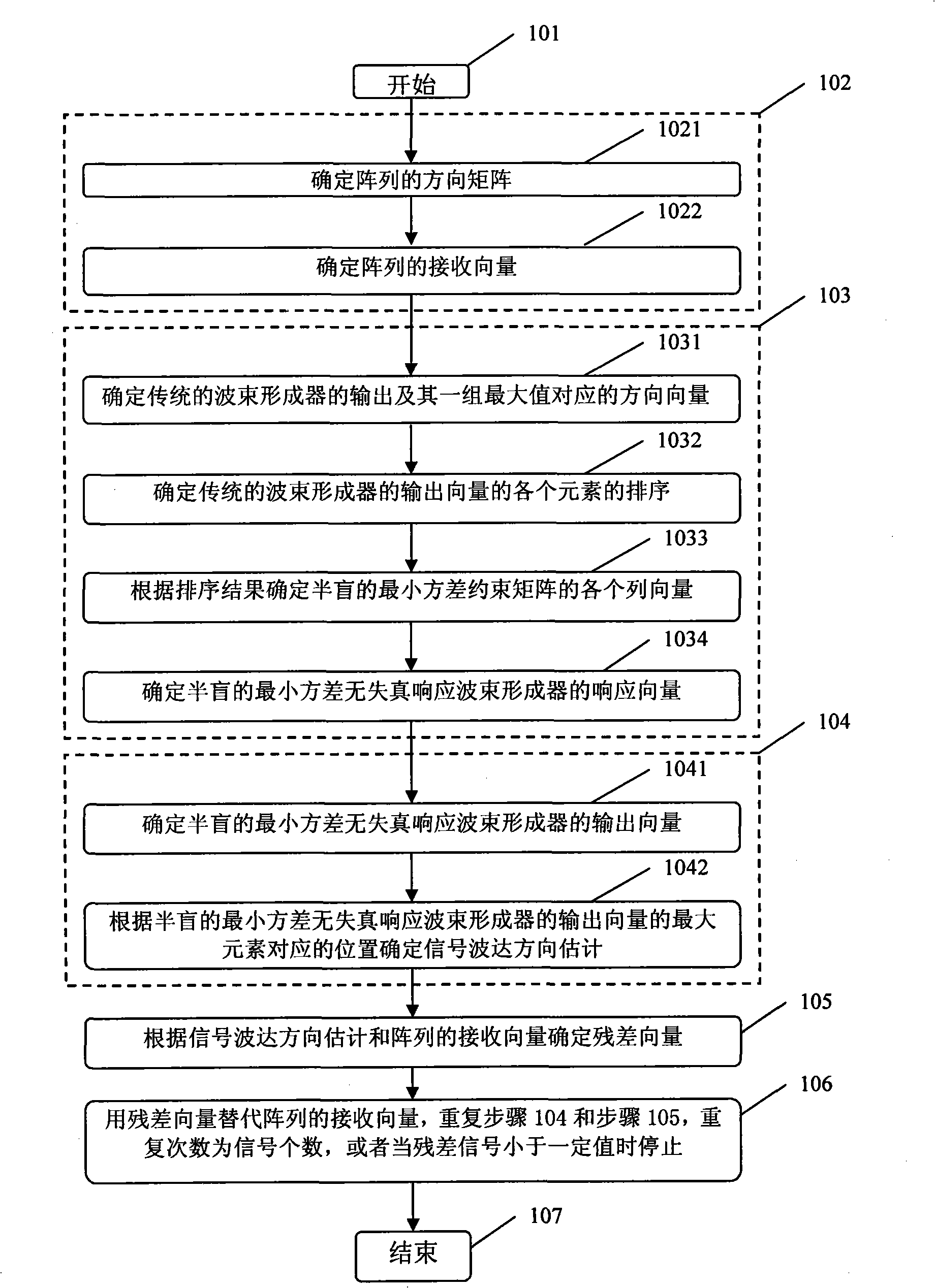
A semi-blind MVDR (minimum variance distortionless response) beams forming method belongs to the array signal processing field of a beam former receiving wireless signals. A group of direction vectors with corresponding maximum values sent out from a traditional beam former is adopted to form a minimum variance constraint matrix and define a semi-blind MVDR beam former response vector satisfying the linear constraint and minimum variance constraint; a signal DOA is estimated according to the DOA corresponding to the maximum value of a projection on the semi-blind MVDR beam former response vector by an array receiving vector; a residual vector is defined in virtue of the signal DOA and the array receiving vector and the residual vector is adopted to displace the array receiving vector to repeat the above steps and the repetition time equals the number of signals or the repetition is stopped when the residual signal is less than a certain value. The method realizes the high accurate and high resolution estimation to the DOA when the number of the array receiving vectors is less, thus realizing the high accurate beam forming.

Description

Technical field [0001] The invention belongs to sensor array signal processing for receiving wireless propagation signals, and relates to an array signal processing method received by a beamformer, in particular to a semi-blind minimum variance non-distortion response beamforming method. Background technique [0002] Beamformers are widely used in radio monitoring, wireless communication, radio astronomy and other fields. The array signal processing involved, especially the method of beamforming, is the core of beamformers, and the accurate direction of arrival estimation of wireless propagation signals is a high Accurate, high-resolution beamformers are the key. [0003] Today, when the array signal processing technology for receiving wireless propagation signals is widely used, high-resolution and accurate direction-of-arrival estimation has important application value in wireless positioning, target tracking, navigation and wireless signal reception. Common methods for e...

Claims


Application Information

Patent Timeline
Patent Type & Authority Applications(China)
IPC IPC(8): G01S3/00H04B7/06
Inventor 万群黄安民刘翼鹏桂冠张瑛杜亚平
Owner UNIV OF ELECTRONICS SCI & TECH OF CHINA
Learn More