
Electric connector terminal and manufacturing method thereof

A technology for electrical connectors and terminals, which is applied in the field of electrical connector terminals and its manufacturing, can solve the problems of insufficient elastic deformation, uneven force, small elastic deformation, etc., achieve low cost, good clamping force, and simple manufacturing method Effect

Inactive Publication Date: 2011-05-18
DEYI PRECISION ELECTRONIC IND CO LTD PANYU
View PDF1 Cites 0 Cited by
  • Summary
  • Abstract
  • Description
  • Claims
  • Application Information

AI Technical Summary

Problems solved by technology

[0004] However, this connector terminal has the following disadvantages: the deformation generated when the pins contact the terminal depends on the elasticity of the material itself, and the elastic deformation that can be produced is small. When the force is uneven, the pins are prone to twist
The elastic arm provided on the terminal of the electrical connector can provide sufficient elastic deformation when the pins are inserted and mated. However, the sufficient elastic deformation provided by the terminal is exchanged for the great waste of metal sheets.
[0006] In view of the above-mentioned existing connector terminals, there may be insufficient elastic deformation provided, and the shortcomings of being easily twisted, or although sufficient elastic deformation can be provided, it is at the cost of wasting materials, so it is necessary to improve the existing connector terminals and Its manufacturing method is further improved

Method used


Image

  • Electric connector terminal and manufacturing method thereof
  • Electric connector terminal and manufacturing method thereof
  • Electric connector terminal and manufacturing method thereof

Examples


Embodiment Construction

[0035] In order to facilitate a better understanding of the present invention, the present invention will now be further described.

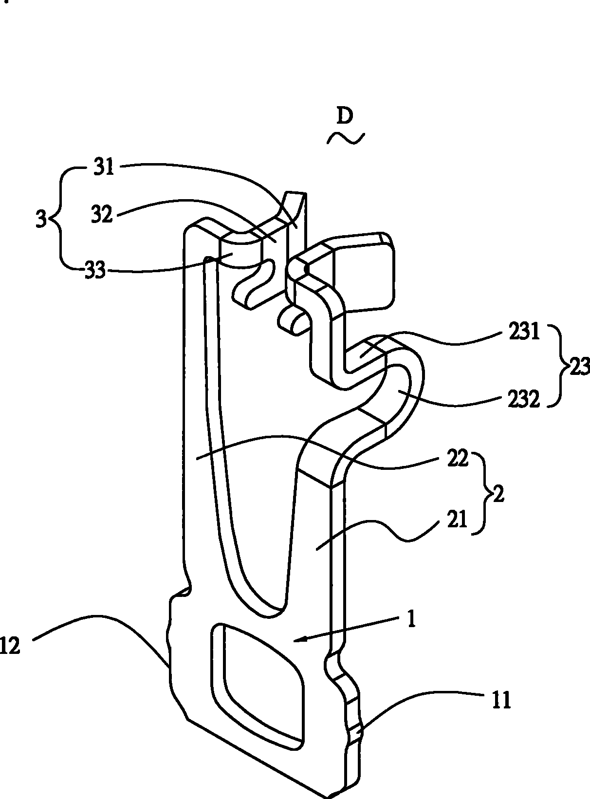
[0036] see Figure 3 to Figure 10 , the electrical connector terminal D of the present invention is mainly used for electrically connecting chip modules (not shown) and circuit boards (not shown), such as image 3 As shown, the electrical connector terminal D is formed by stamping, bending, electroplating, and removing residual material strips from a metal plate. The electrical connector terminal D includes a main body 1, two terminal arms 21, 22 , Two contact parts 3 .

[0037] The main body 1 is located at the bottom of the electrical connector terminal D, and can be used to solder the electrical connector terminal D to a circuit board (not shown). The two side edges 12 of the main body 1 are provided with at least one protrusion 11 for interference Hold the terminal D of the electrical connector.

[0038] Two terminal arms 21, 22 extend ve...


PUM


Abstract

The invention discloses an electric connector terminal and a preparation method thereof; the electric connector terminal is used for contacting with the pin which is inserted for matching; the connector terminal comprises a mainbody, two terminal arms which are relatively arranged by extending out of the same end of the mainbody; at least one terminal arm of the two terminal arms is provided witha bending part which is formed by that the longer terminal arm is bent in a direction vertical to the vertical direction so as to lead the two terminal arms to be almost in the same height; the connector terminal also comprises two contact parts which are relatively arranged by extending out of the other end of the terminal arm. The electric connector terminal and the preparation method of the invention have the advantages of simpleness, low cost, and providing enough elastic deformation and good clamping force.

Description

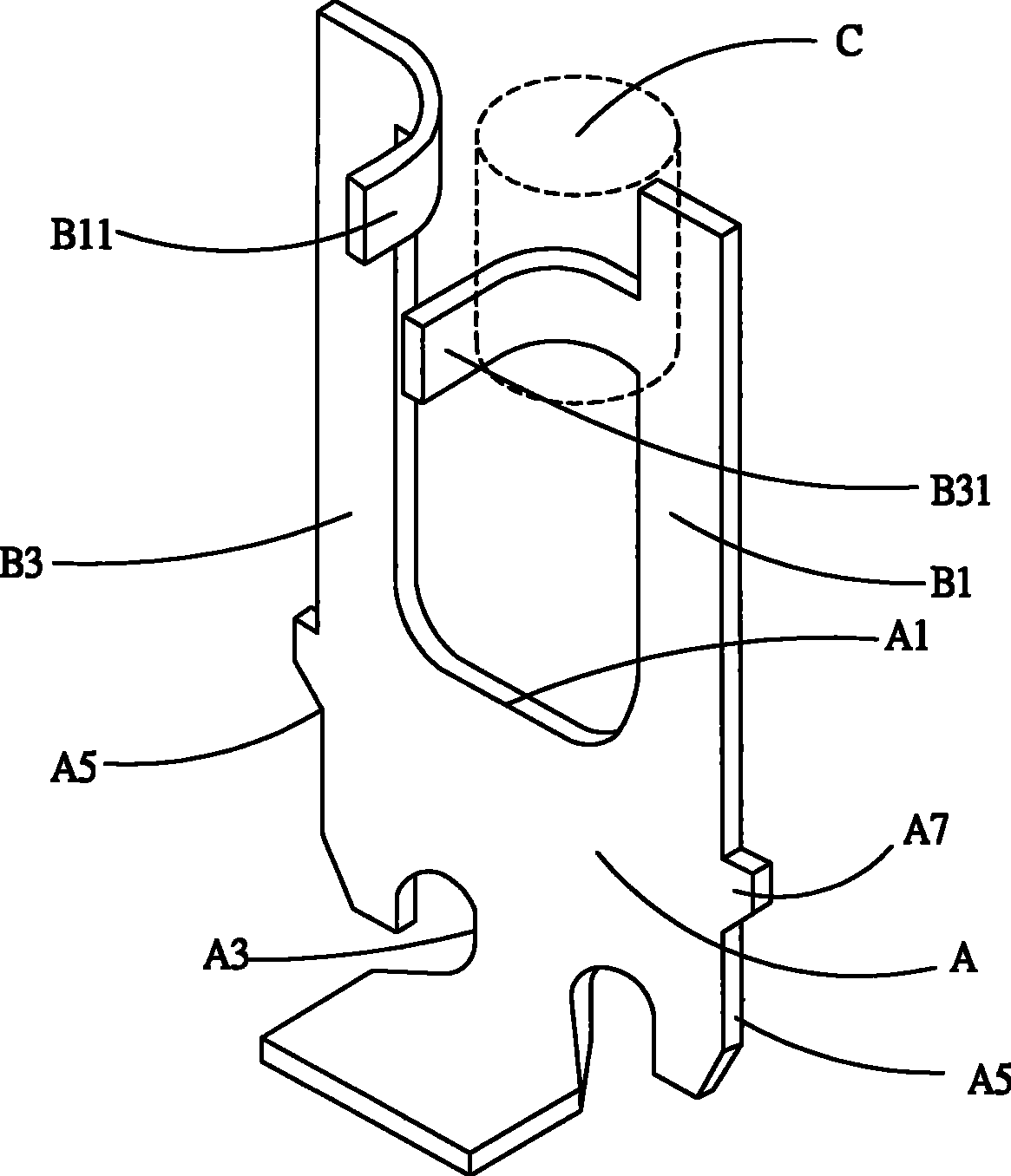
【Technical field】 [0001] The present invention relates to an electrical connector terminal and a manufacturing method thereof, in particular to a conductive terminal of an electrical connector for electrically connecting a chip module and a circuit board and a manufacturing method thereof. 【Background technique】 [0002] The comparative document CN2537141Y discloses an existing electrical connector terminal for electrically connecting chip modules and circuit boards, such as figure 1 As shown, the electrical connector terminal has a body A having upper and lower edges A1, A3 and a side edge A5 connected to the upper and lower edges A1, A3. The side edge A5 of the body A is formed with a barb A7, and two relatively soft elongated support parts B1, B3 protrude from the upper edge A1 of the body A, and the support parts B1, B3 are spaced apart from each other and are located on the same plane as the body A superior. Each support portion B1, B3 is respectively extended with a ...

Claims


Application Information

Patent Timeline
Patent Type & Authority Patents(China)
IPC IPC(8): H01R13/11H01R12/55H01R33/74H01R43/16H01R12/57H01R12/71
Inventor 曹军
Owner DEYI PRECISION ELECTRONIC IND CO LTD PANYU
Learn More