
Fault location method and system for passive optical network

A passive optical network and fault location technology, applied in the field of network communication, can solve problems such as difficulty in quickly and accurately locating passive optical networks, and achieve the effect of enhancing fault location capabilities and improving maintainability

Active Publication Date: 2011-07-20
HUAWEI TECH CO LTD
View PDF0 Cites 0 Cited by
  • Summary
  • Abstract
  • Description
  • Claims
  • Application Information

AI Technical Summary

Problems solved by technology

[0007] The purpose of the embodiments of the present invention is to provide a fault location method for a passive optical network, aiming to solve the problem in the prior art that it is difficult to quickly and accurately locate a fault in a passive optical network

Method used


Image

  • Fault location method and system for passive optical network
  • Fault location method and system for passive optical network
  • Fault location method and system for passive optical network

Examples


Embodiment Construction

[0023] In order to make the object, technical solution and advantages of the present invention clearer, the present invention will be further described in detail below in conjunction with the accompanying drawings and embodiments. It should be understood that the specific embodiments described here are only used to explain the present invention, not to limit the present invention.

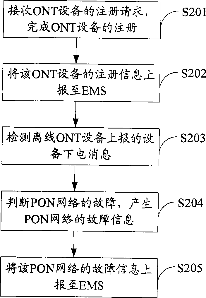
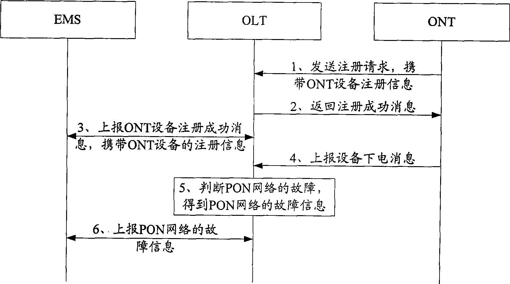
[0024] In the embodiment of the present invention, when the access terminal device is powered off or powered off normally, a flag is sent to the central access device of the PON network. The device power-off message that causes the access terminal device to suddenly wire, the central access device of the PON network judges whether it detects the device power-off message, It can judge whether the fault in the PON network occurs on the main line or in the access terminal device by checking whether the terminal device is normally online, which enhances the fault location capability of the PON network....


PUM


Abstract

The invention adapts to network communication field and provides a fault positioning method for passive optical network comprising following steps of checking off-line information reported by off-line access device, judging if there is failure of the off-line access terminal device or main trunk circuit connected with off-line access terminal device according to checking result and on-line statusof access terminal device of the same center access device port with the off-line access terminal device. In the present example, when access terminal device is off-line or normally switched off, a off-line message is produced. PON network failure is quickly and accurately judged by checking if the device has received off-line message and on-line status of other access terminal device of the samecenter access device port with the off-line access terminal device.

Description

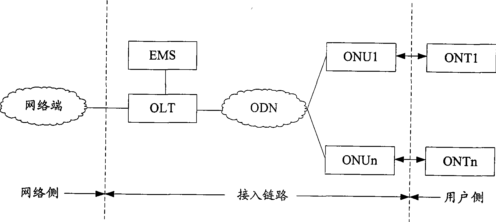
technical field [0001] The invention belongs to the field of network communication, and in particular relates to a fault location method and system of a passive optical network. Background technique [0002] Passive Optical Network (PON) refers to the network element management system (Element Management System, EMS), optical line terminal (optical line termination, OLT), optical distribution network (Optical Distribution Network, ODN) and optical network A passive electronic equipment system composed of Optical Network Unit (ONU) is a mainstream optical fiber access network. [0003] figure 1 It shows a typical configuration of a passive optical network, in which the OLT is the central access device of the passive optical network, provides the interface between the network side and the service node for the optical access network, and communicates with the user side through one or more ODNs ONT equipment (that is, access terminal equipment) communication; ODN provides opti...

Claims


Application Information

Patent Timeline
Patent Type & Authority Patents(China)
IPC IPC(8): H04B10/08
CPCH04J3/14H04J3/1694
Inventor 罗成
Owner HUAWEI TECH CO LTD
Learn More