

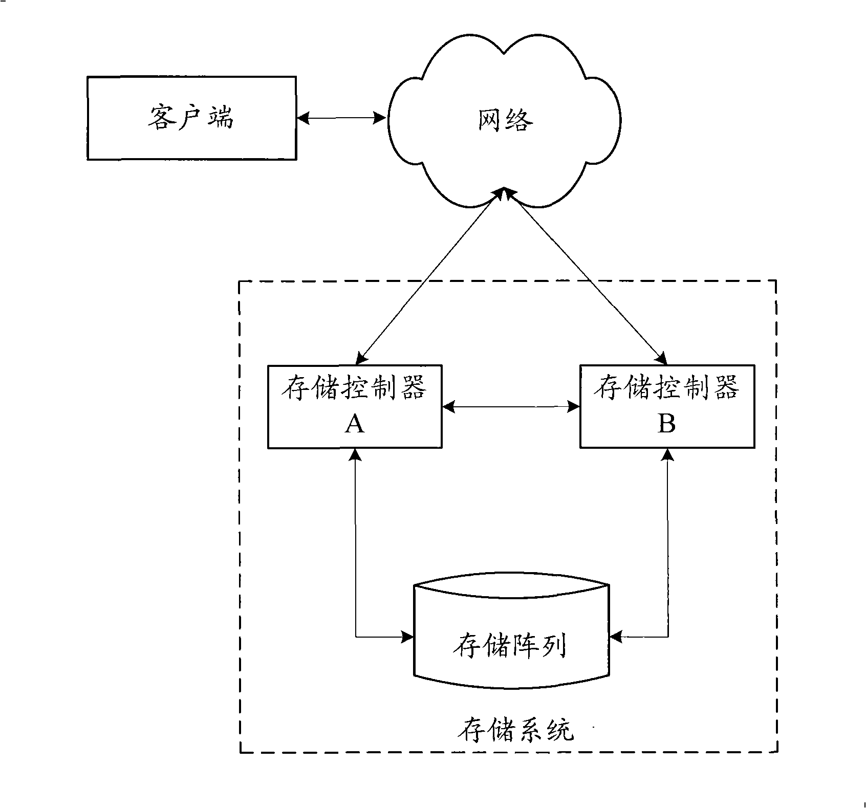
Load equalization implementing method, storage control equipment and memory system
A technology of storage control and implementation method, applied in the direction of storage and forwarding switching systems, transmission systems, electrical components, etc., can solve the problems of unbalanced load between storage controllers A and B, and cannot effectively achieve load balancing, and achieve dynamic load balancing. Effect
- Summary
- Abstract
- Description
- Claims
- Application Information
AI Technical Summary
Problems solved by technology
Method used
Image


Examples
example 1
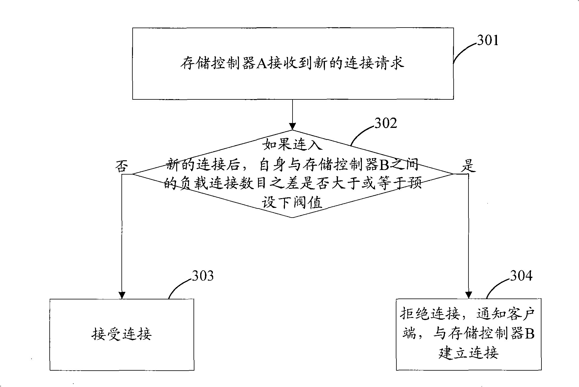
[0103] Example 1. Assume that a new connection request is added to storage controller A; when a new connection is added, a lower threshold value of 5 should be selected.
[0104] Storage controller A calculates that the number of load connections after adding new connections is 11; the difference between the load connections between storage controllers A and B is 11-6=5, and the difference of 5 load connections is equal to the lower threshold value 5. Therefore, storage Controller A rejects new connections to join. Storage controller A sends a target moved reply message to the client, and the reply message carries the IP address of storage controller B. After receiving the targetmoved reply message, the client sends a connection request to storage controller B. After receiving the request, storage controller B calculates the number of load connections after adding new connections as 7, and the difference between load connections between storage controller B and A is 7-11=-4. ...
example 2
[0105] Example 2. Assume that two loads in the storage controller B are disconnected; when the existing connection is disconnected, the lower threshold value 5 should be selected.
[0106] The load connection data of storage controller B changes to 4; storage controller A learns that the number of load connections of storage controller B has decreased, and the number of idle connections remains unchanged, so it is determined that any existing load connection in storage controller B is disconnected, and storage controller B The difference of the load connections between the controllers A and B is 10-4=6, and the difference 6 of the load connections is greater than the lower threshold value 5, therefore, the storage controller A selects (6-5+1) / 2 from the load connections. = 1 load connection, actively drop the selected load connection. Afterwards, the client sends a connection request to storage controller B according to the target moved reply message sent by storage controller...
example 3
[0107] Example 3. It is assumed that an idle connection on the storage controller B is converted into a load connection; when switching between an idle connection and a load connection, an upper threshold value of 8 should be selected.
[0108] The number of load connections of storage controller B becomes 7; storage controller A learns that the number of load connections of storage controller B increases and the number of idle connections decreases, so it determines that there are idle connections in storage controller B converted to load connections, and storage controller B The load connection difference between A and B is 10-7=3, and the load connection difference 3 is less than the upper threshold value 8, and no operation is required.
PUM
 Abstract
Description
Claims
Application Information