Device for limiting the advance during a drilling operation

A drilling operation, step drill bit technology, applied in drilling/drilling equipment, components of boring machine/drilling machine, positioning measurement in boring machine/drilling machine, etc. The effect of trimming and preventing damage

Inactive Publication Date: 2009-01-14
AIRBUS OPERATIONS GMBH
View PDF0 Cites 2 Cited by
  • Summary
  • Abstract
  • Description
  • Claims
  • Application Information

AI Technical Summary

Problems solved by technology

In this regard, on the one hand, a countersink recess that is too deep leads to rejection, and on the other hand, a countersink recess that is too small in depth necessitates complex resurfacing

Method used


Image

  • Device for limiting the advance during a drilling operation
  • Device for limiting the advance during a drilling operation

Examples


Embodiment Construction

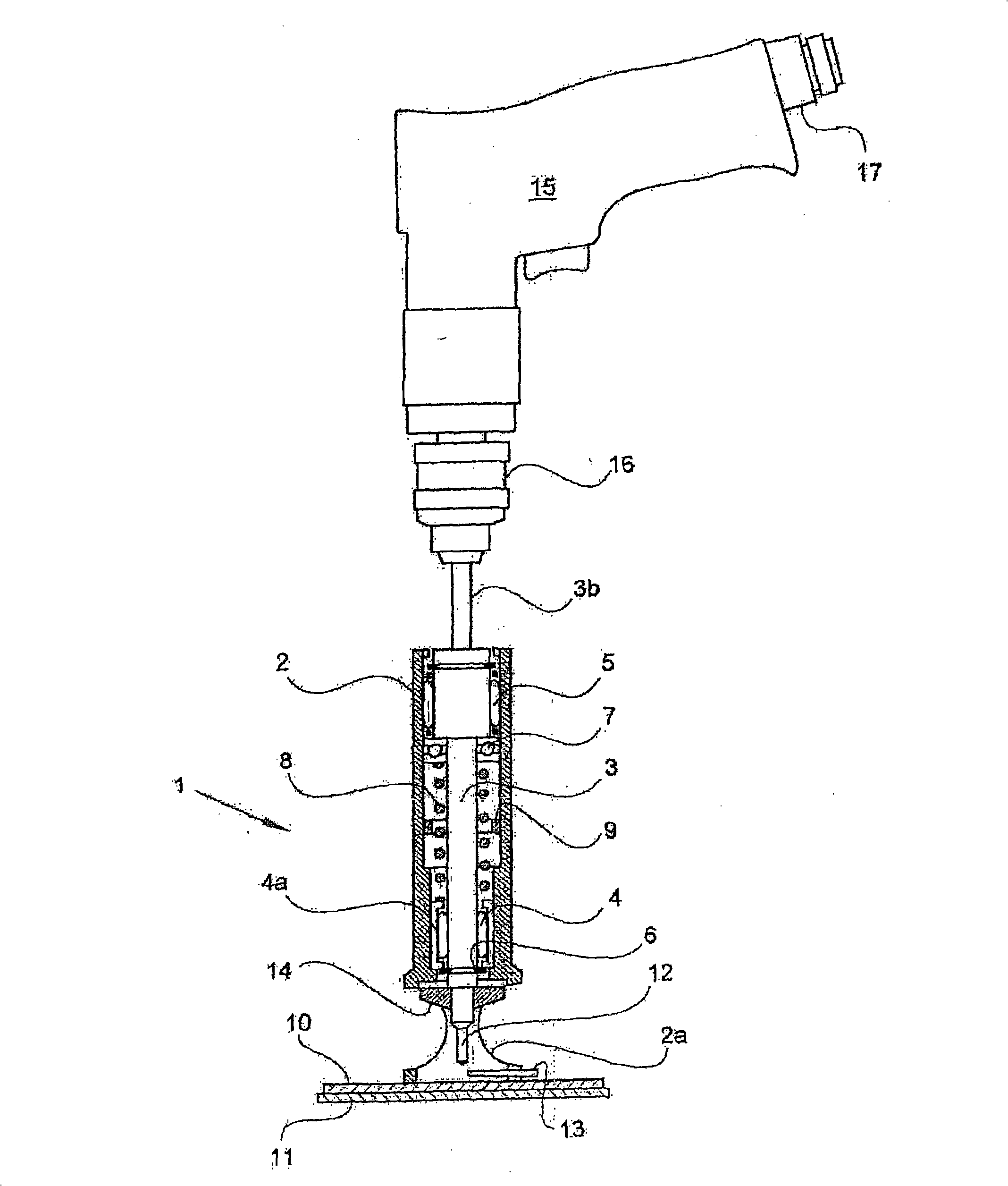
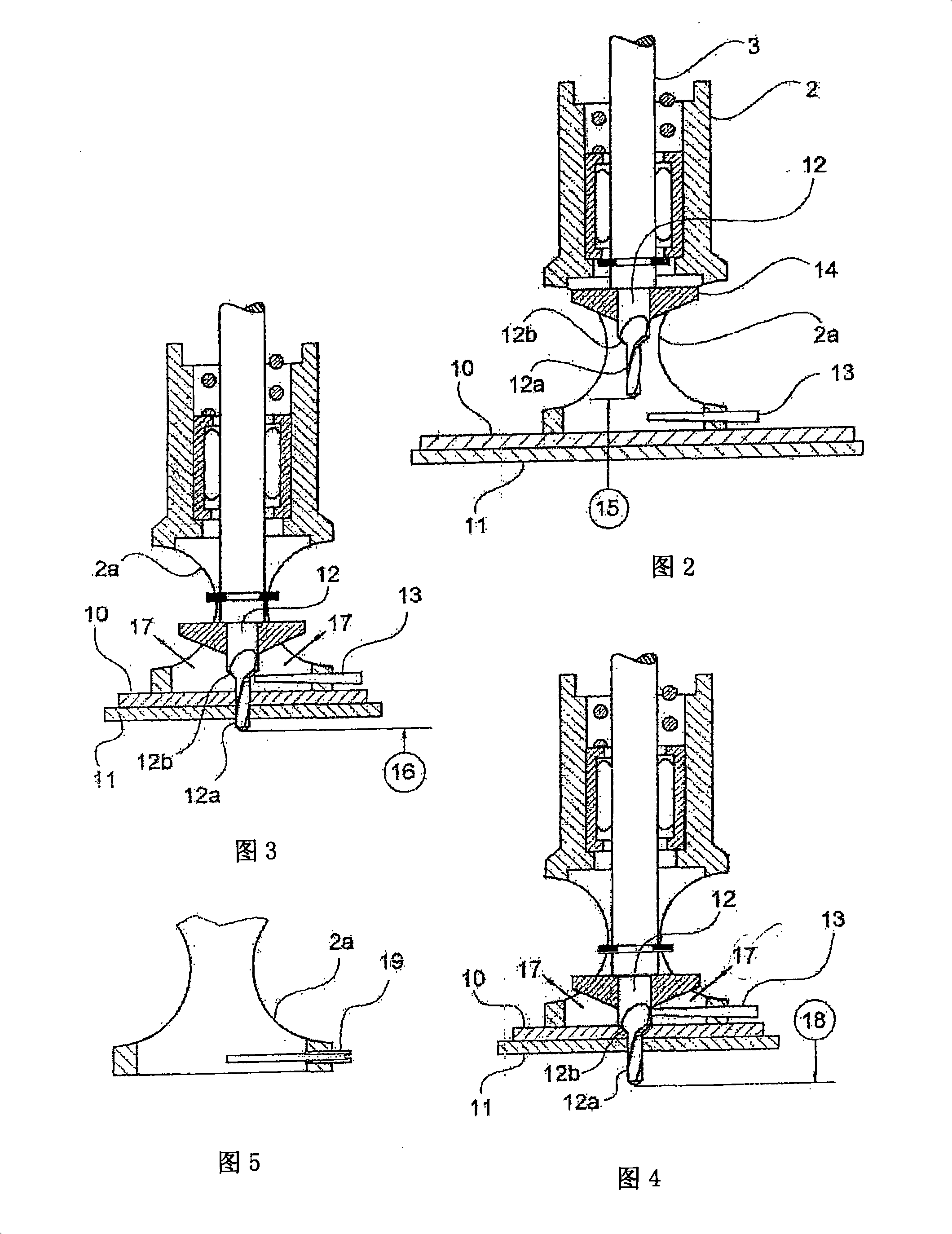
[0012] figure 1 There is shown a device 1 of a known kind for limiting advancement by connection, for example, with a hand drill, the device 1 comprising a housing 2 and a shaft 3 rotatably mounted therein with a widened portion 3a and a shank portion 3b. The lower needle bearing 4 and the upper needle bearing 5 are used for mounting the shaft 3 . The shaft 3 is shown in its upper position. In this position, the axial confinement ring 6 arranged on the shaft 3 bears against the part 4a of the needle bearing 4 fixed to the housing. The lower end of the widened portion 3 a forms a shoulder against which the thrust ball bearing 7 abuts. Compression spring 8 , for its part supported with its lower end against part 4 a of needle bearing 4 fixed to the housing, acts on thrust ball bearing 7 from below in the figure. An axially adjustable stop 9 is arranged inside the housing 2 . The compression spring 8 is dimensioned such that, shown as a result of the prestressing, the shaft 3...


PUM


Abstract

In a device for limiting the advance of a drill during a drilling operation, which can be used in conjunction with a hand drill (15) or with an automatic manufacturing machine, the device comprising a housing (2) with a stop cage (2a) and a spindle (3) mounted rotatably and axially displaceably in the housing, and a stop (9) which is adjustable in the axial direction being arranged for limiting the advance, the invention consists in that the stop cage (2a) comprises a chip breakes (13) for breaking the chips, with a housing-side end and a free end, in such a way that it extends approximately parallel and directly adjacent to the workpiece surface and approximately radially from the outside towards the drilling tool (stepped drill bit 12) in such a way that its free end almost touches the countersink (12b) . Damage to the surface of workpieces is prevented by the invention, so that corresponding refinishing is avoided. Moreover, the removal of the coiled chips from the drilling tool previously necessary after each drilling cycle is dispensed with.

Description

technical field [0001] The present invention relates to a device for limiting advance during drilling operations, operable in combination with hand drills and numerically controlled automatic machining machines. Background technique [0002] Such a device comprises, for example, a cylindrical housing with a rotatably mounted shaft in which the shaft is arranged coaxially with a drive-side end and a tool-side end, which in There is limited mobility in the axial direction. The drive end of the shaft is designed in such a way that it can be clamped into the drill chuck of a hand drill or into a corresponding receiver of an automatic machining machine. The tool-side end of the shaft is internally threaded and can be screwed into a suitable drilling tool. A connecting drill and a countersink, known as a step drill, are used as drilling tools in combination with devices of this kind. The drilling tool is surrounded by a stop cage, which is fixed to the housing and has side open...

Claims


Application Information

Patent Timeline
Patent Type & Authority Applications(China)
IPC IPC(8): B23B47/34
CPCY10T408/50B23B51/104Y10T408/5653B23B49/005Y10T408/18B23B2251/48B23B47/34Y10T408/8925
Inventor 马歇斯·克鲁斯劳尔夫·克劳森托马斯·古森沃夫刚·赫兹
Owner AIRBUS OPERATIONS GMBH
Why Eureka
Try Eureka