Noise barrier especially for a high-speed railway line

A technology for high-speed railways and sound barriers, which is applied in noise absorption devices, buildings, etc., can solve the problem of high installation cost of sound insulation components and achieve reliable assembly costs.

Inactive Publication Date: 2009-01-21
旭普林工程股份公司
View PDF0 Cites 15 Cited by
  • Summary
  • Abstract
  • Description
  • Claims
  • Application Information

AI Technical Summary

Problems solved by technology

Due to the aerodynamic loads that arise, the production of the sound insul

Method used


Image

  • Noise barrier especially for a high-speed railway line
  • Noise barrier especially for a high-speed railway line
  • Noise barrier especially for a high-speed railway line

Examples


Embodiment Construction

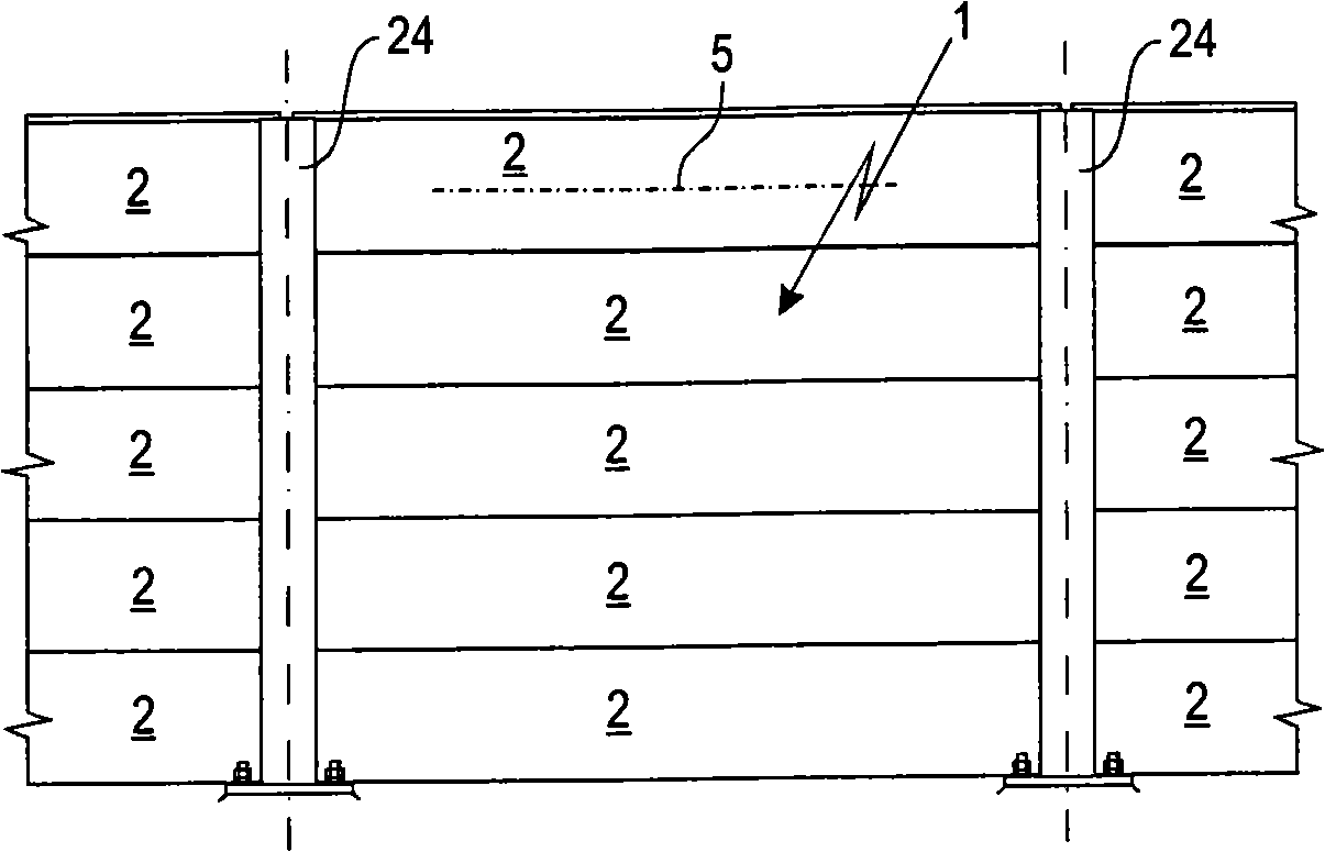
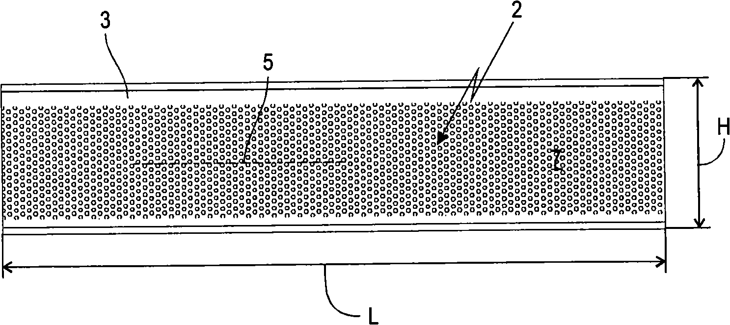
[0029] figure 1 A sound barrier 1 according to the invention is shown in side view, which is formed from a plurality of uprights 24 with panel-type sound insulation elements 2 located therebetween. In this exemplary embodiment, the columns 24 each have a screw flange at their lower end, by means of which the columns are fastened to a base not shown in detail. Expediently, the columns 24 can also be inserted into the foundation, cast in concrete or fixed in some other way. Each sound insulation element 2 is designed as an elongated plate which extends along a longitudinal axis 5 . The longitudinal axis 5 runs horizontally between the columns 24 . Five sound insulation elements 2 are respectively stacked between two adjacent columns 24 . Other quantities may also be suitable. For installation, the column 24 is first erected, and then the sound insulation elements 2 are inserted from above between the sides 27 , 28 shown in FIG. 6 of the column 24 and stacked on top of each o...


PUM


Abstract

The invention relates to an acoustic barrier especially used for high speed railway. The acoustic barrier comprises multiple acoustic insulation components (2); the acoustic insulation components (2) comprises a plate shell (3) having an acoustic insulation liner (4) and a hollow transverse section crossing the longitudinal axis (5). The surrounding walls (6, 7, 8, 9) of the plate shell (3) consist of at least on plate (10, 11) formed by folding the hollow transverse section.

Description

technical field [0001] The invention relates to a sound barrier, in particular for high-speed railways, having a plurality of sound-insulating elements, wherein the sound-insulating elements comprise a sheet-metal shell with a sound-insulating insert. Background technique [0002] Noise barriers of known construction generally consist of uprights which are erected at regular intervals, for example along roads, industrial installations or railways, and between which plate-shaped sound insulation elements are placed. Such a sound-insulating element comprises a sheet-metal housing, in particular made of aluminum sheet, in the interior of which a sound-insulating insert is fastened. To form the sheet metal shell, the metal sheets are multidimensionally formed on a rolling mill by rolling etc. and assembled to form a sheet metal shell. [0003] Noise barriers for railways are constructed relatively close to the track. In the case of high-speed railways, sound insulation element...

Claims


Application Information

Patent Timeline
IPC IPC(8): E01F8/00
CPCE01F8/007E01F8/0011
Inventor H·威德曼
Owner 旭普林工程股份公司
Why Eureka
Try Eureka