
Engine noise barrier

a technology for engine noise and shields, which is applied in the direction of intake silencers for fuel, combustion air/fuel air treatment, machines/engines, etc., can solve the problems of manufacturing and performance problems, unsatisfactory noise attenuation provided by such shields, and one has taken the approach

Inactive Publication Date: 2003-04-03
BASF AG
View PDF0 Cites 10 Cited by
  • Summary
  • Abstract
  • Description
  • Claims
  • Application Information

AI Technical Summary

Benefits of technology

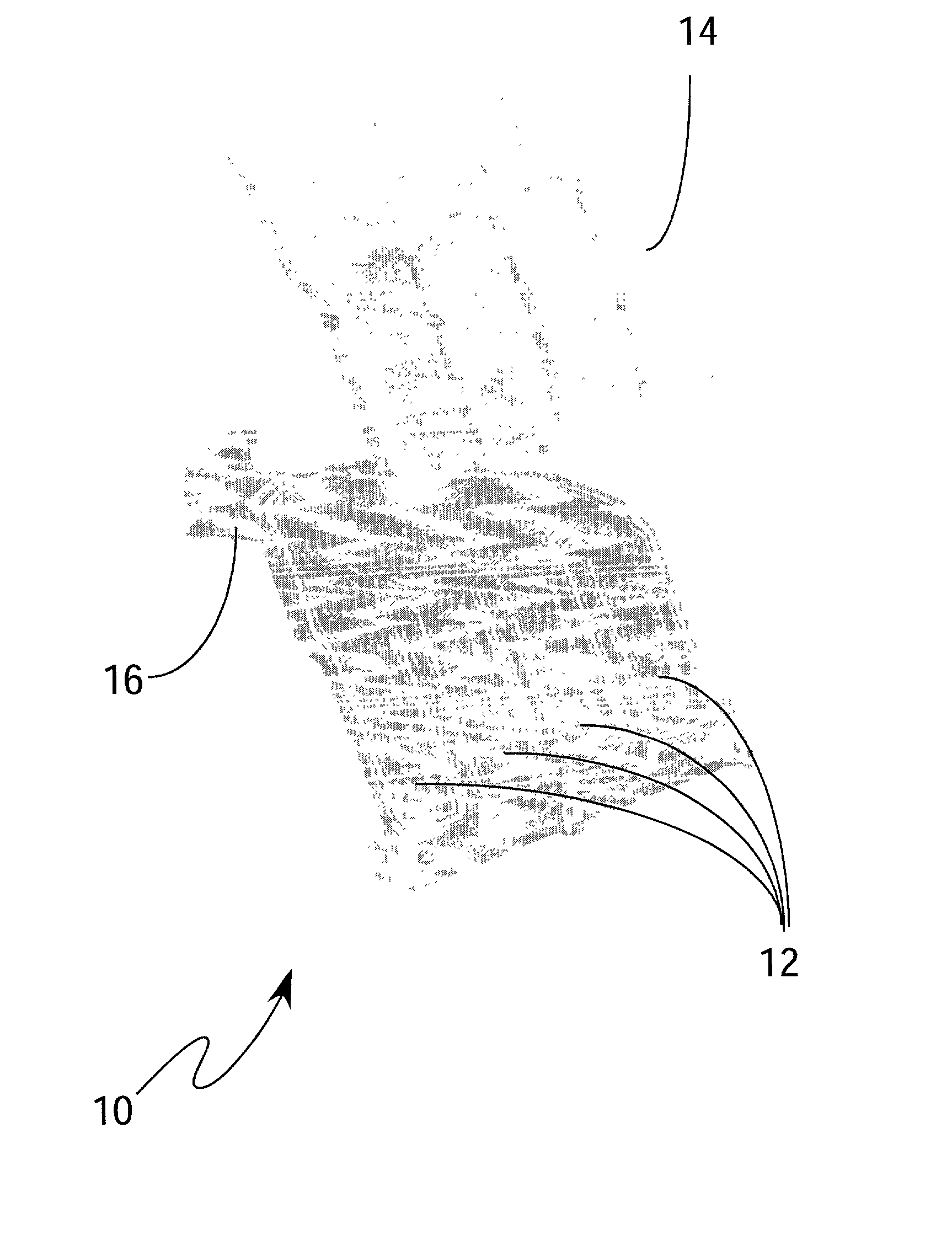
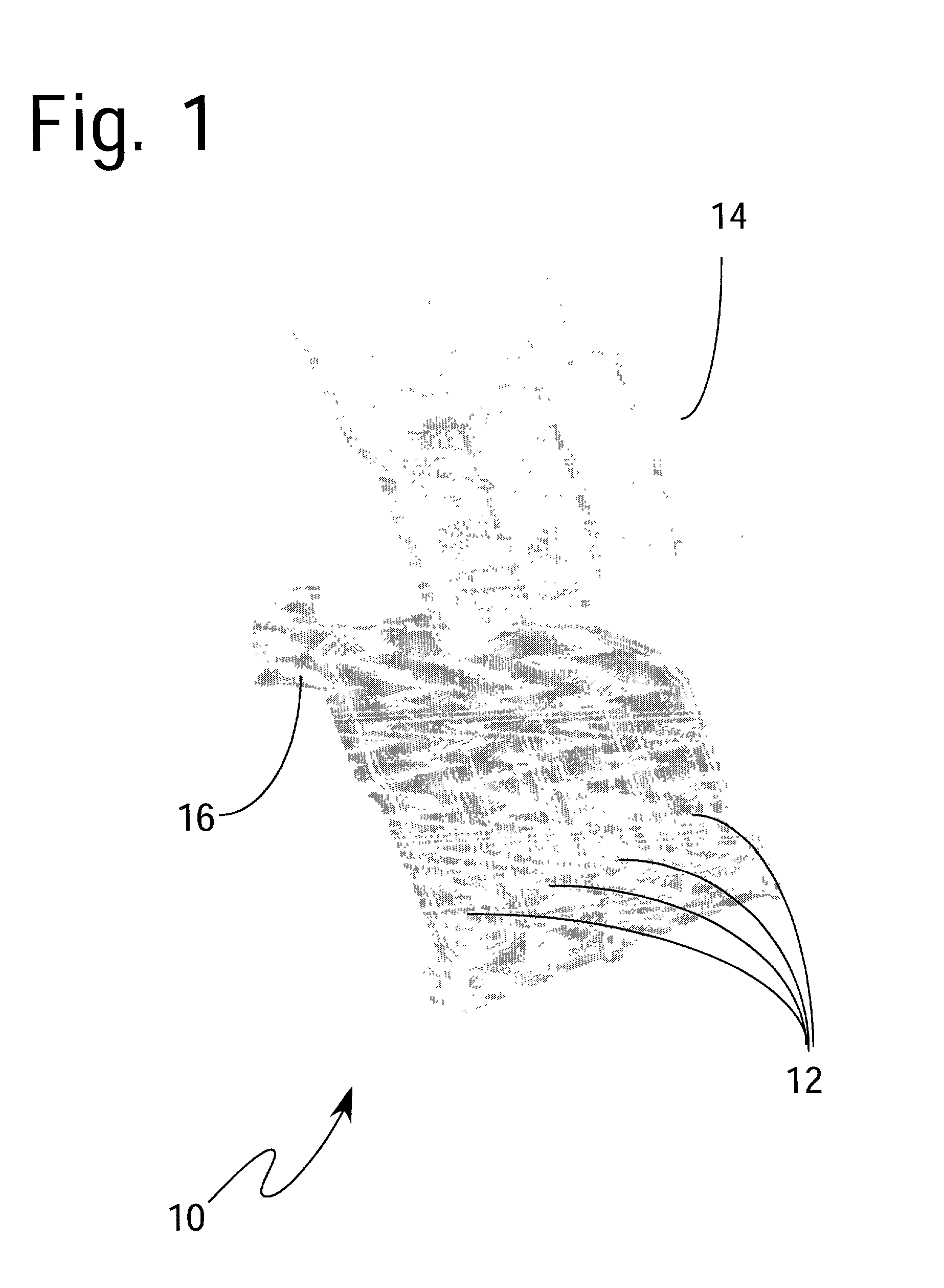
[0011] Optionally, the layers are provided with a plurality of blisters to distribute localized increased core thickness (pockets) at predetermined locations across the air intake manifold shell surface, the locations being selected to increase noise transmission losses. The noise transmission loss is further improved by introducing higher density materials into the localized pockets.
[0013] In yet another embodiment, a single layer air intake manifold shell is comprised of a polyamide resin containing glass and mineral fillers such as barium sulfate or high damping carbon nano-tubes. Optionally, the single layer air intake manifold shell has non-uniform thickness. The thickness is preferably greatest over preselected areas from which emanate noise transmissions having larger amplitude, to increase noise transmission losses.
[0014] The present invention incorporates barrier and absorption technologies in plastic constructions thereby reducing overall noise transmittance while at the same time reducing space, weight and cost requirements of existing technologies.

Problems solved by technology

While materials such as nylons have been used in air intake manifold applications, such attempts to meet automotive needs have encountered manufacturing and performance issues; there remains significant room for improvement in low cost noise abatement air intake manifolds.
These all require post injection molding operations and are therefore costly.
In addition, the noise attenuation provided by such shields has been unsatisfactory.
No one has taken the approach of incorporating the noise shielding function into the plastic component itself, such as utilizing co-injection technology, and vibration welding to improve noise abatement performance at a lower cost.
Nor have superior sound transmission loss materials been used in air intake manifold shell fabrication.
Optionally, the single layer air intake manifold shell has non-uniform thickness.
Having a lower critical frequency reduces the effective range of application of the material.
Thus, the double wall resonant frequency in the low frequency region, and the critical frequency of the individual walls at the high frequency limit the effectiveness of the double wall system.
This coupling material can significantly increase sound transmission loss, and introduce a damping effect to the mass-air-mass (f.sub.dw) and cavity resonances.
This approach, may not be practical from manufacturing consideration as a significant weight and cost increase occurs.
In addition to the increase in mass, the critical frequency of the material is lowered, which is not desirable.

Method used


Image

  • Engine noise barrier
  • Engine noise barrier
  • Engine noise barrier

Examples


Embodiment Construction

Kg / m.sup.2 (lb / ft.sup.2) 1 XA2934 nylon 6 based polymer: 6.0 (1.2) Single Wall 2 XA2935 nylon 6 based polymer: 6.3 (1.3) Single Wall 3 8233G HS BK 102 nylon 6 based polymer: 4.0 (0.8) Single Wall 4 8233G HS BK 102 nylon 6 based polymer: 8.0 (1.6) Double Wall (2 layers separated by 6 mm air gap)

[0071] A thin lead panel of 4.9 Kg / m.sup.2 (1.0 lb / ft.sup.2) surface weight was used to compute the correlation factor as referenced in SAE J1400. The lowest usable frequency band of measurement for this test (in a 508 mm by 508 mm, or 20 inch by 20 inch opening) is 125 Hz (based on the 0.72 m or 2.36 ft) diagonal of the opening between the source room and the receiving room.

[0072] Measurements were made at six microphone locations in the source room and at one location 100 mm (4 inches) away from the sample, six times in the receiving room.

[0073] STL data obtained from the samples clearly show the increase in performance obtained using the new material over the existing Capron.RTM. 8233 resin...


PUM

PropertyMeasurementUnit
Percent by massaaaaaaaaaa
Thicknessaaaaaaaaaa

Abstract

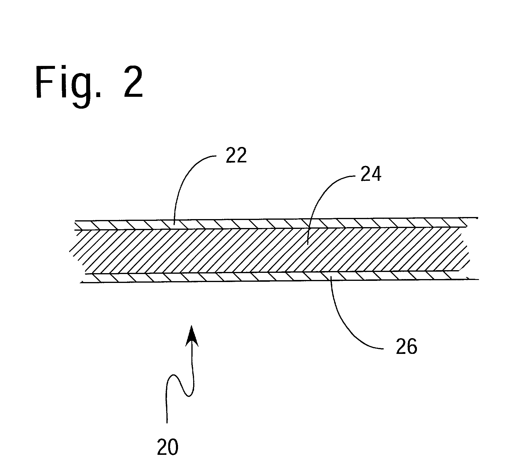
A co-injection molded air intake manifold shell comprises an inner and outer skin layer separated by a sound absorbing or sound insulation core. Each skin layer is composed of a polyamide resin which, optionally, contains glass fiber reinforcement and high specific gravity fillers such as barium sulfate or tungsten. The sound insulating core is composed of a high density material having a foam structure, such as a polyamide resin. Skin layers are provided with a plurality of pockets to permit distribution of localized lumped masses at predetermined locations tailored to increase noise transmission losses. A single layer air intake manifold shell having non-uniform thickness is also provided. The thickness of the single layer air intake manifold shell is larger over preselected noise sources of larger amplitude to maximize noise attenuation for a nominal air intake manifold shell thickness.

Description

[0001] 1. Field of the Invention[0002] The present invention relates to sound attenuation systems that restrict airborne and structural-borne sound wave transmission; and more particularly, to an air intake manifold shell having a combination of compositional and structural features that significantly reduce engine induced noise.[0003] 2. Description of the Prior Art[0004] Continued efforts to reduce vehicle weight and cost have led automobile manufactures to replace metal components with alternative materials. Plastic air intake manifolds represent one example of this trend. These air intake manifolds cost and weigh less thus reducing manufacturing costs while increasing fuel efficiency. Air intake manifolds currently sold to original equipment manufacturers are segregated into several feature categories. Significant feature categories typically considered include cost, temperature performance, aesthetics, recycling aspects and noise abatement performance.[0005] While materials suc...

Claims


Application Information

Patent Timeline
IPC IPC(8): B32B27/20F02M35/12B32B27/34F02M35/10F02M35/104
CPCB32B27/20B32B27/34F02M35/10268F02M35/10321F02M35/10327F02M35/1283F02M35/1036F05C2225/08F02M35/1272F02M35/1277F02M35/10347
Inventor HOMSI, EMILE N.KROLICK, THOMAS J.LEE, CHUL S.HAN, PETER K.KAGAN, VAL A.
Owner BASF AG
Learn More