Noise Barrier And A Method Of Construction Thereof

a technology of noise barrier and construction method, which is applied in the field of noise barrier, can solve the problems of high wind load on such noise barrier structures, energy and laborious erection and mobilization of such heavy noise barrier structures, and energy and laborious dismantling of such heavy structures, so as to achieve simple construction of noise barrier, relieve the need for cranes, and reduce the effect of noise barrier

Active Publication Date: 2015-09-24
ACOUSTICS INNOVATION
View PDF10 Cites 10 Cited by
  • Summary
  • Abstract
  • Description
  • Claims
  • Application Information

AI Technical Summary

Benefits of technology

[0006]The invention provides the possibility of reducing wind load on the barrier structure during occasional strong gust, where such strong gust only occurs of once in a few months.
[0018]In a fifth aspect, the invention proposes a method of installing a noise barrier comprising the steps of: providing at least one mounting pole, providing a first noise barrier panel, mounting the first noise barrier panel onto the at least one mounting pole, sliding the first noise barrier panel along the at least one mounting pole. This allows the noise barrier to be constructed simply by pushing the noise barrier panel up from the ground, and relieves the need for cranes to lift noise panels into the air for mid-air installation. Accordingly, the noise barrier can now be constructed with less reliance on heavy machinery.

Problems solved by technology

In the outdoors, the wind load on such noise barrier structures can be very high occasionally, such as when there is a strong gust of wind.
A strong concrete foundation is usually required for tall noise barriers of 6 m to 10 m. The erection and mobilization of such heavy noise barriers are energy and labour intensive, and have to be done using cranes and elevated platforms.
Dismantling these heavy structures is also energy and labour intensive.
However, if the source of noise lasts for only a short period of time or moves every few hours or days, which is typical of construction work on underground utilities beneath road surface, it would not be practical to erect and move such noise barriers along with the source of noise.
Moreover, there may be difficulty in obtaining permission to lay a concrete foundation in some places.
Construction of a concrete foundation may also not be allowed at day time due to road congestion, and may be allowable only at night time within a few limited hours.

Method used


Image

  • Noise Barrier And A Method Of Construction Thereof
  • Noise Barrier And A Method Of Construction Thereof
  • Noise Barrier And A Method Of Construction Thereof

Examples


first embodiment

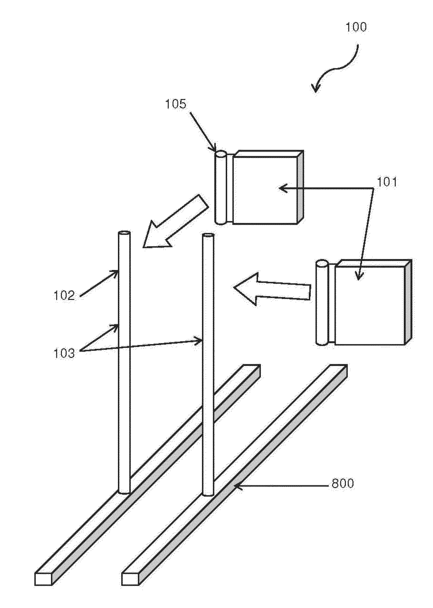
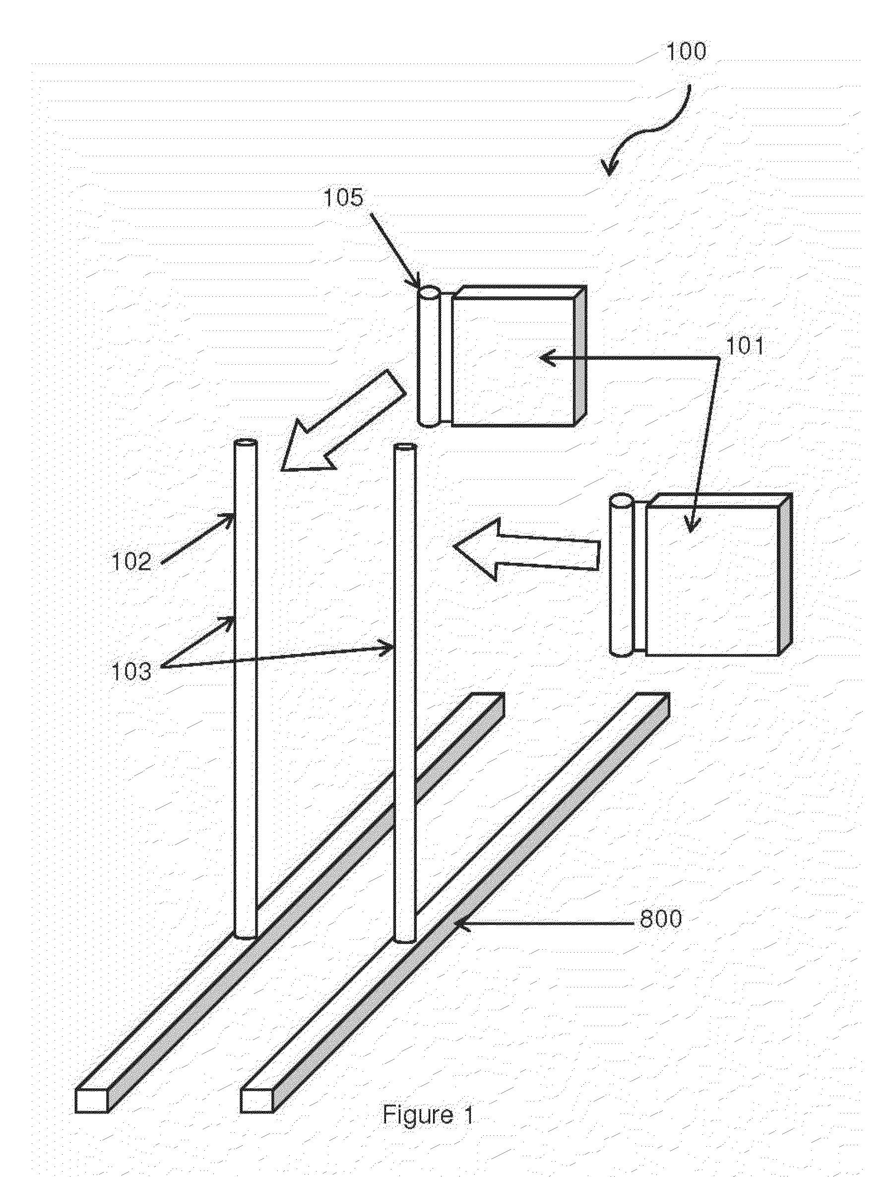
[0049]FIG. 1 is a schematic of an exploded view of a first embodiment, which is a noise barrier 100 having noise barrier panels 101 that can be blown open by wind. This limits the wind load on the noise barrier 100, mounting poles 102 and frame 103, as any instance of undesirably high wind bad is reduced immediately when noise barrier panels 101 are blown open to reduce the noise barrier surface area facing the wind.

[0050]The term ‘wind load’ refers to the pressure or force induced on a structure by wind, and is one of the most critical parameters in outdoor noise barrier design. Wind load is approximately directly proportional to the cross-sectional area of a surface orthogonal to wind direction and square of the wind speed:

F=1 / 2ρV2ACd  (1)

[0051]Where:

[0052]ρ=Density of air V=Wind speed

[0053]A=Cross sectional area orthogonal to wind speed

[0054]Cd=Coefficient of drag F=Force of wind load

[0055]In some embodiments, the reduction of orthogonal surface area possibly reduces the wind loa...

second embodiment

[0088]FIG. 20 show a second embodiment which is a noise barrier 100. The noise barrier 100 has two main parts, namely, flexible noise barrier panels 101 and a frame 103 for mounting the noise barrier panels 101 thereon. The frame 103 provides standing support for noise barrier panels 101 and is made up of a pair of mounting poles 102 erected vertically on the ground.

[0089]The frame 103 is provided with a rail system 2000 for installation of noise barrier panels 101. The rail system 2000 is pivoted to the top of each mounting pole 102. Each rail 2000 is almost as long as the mounting pole 102. The black block arrow in FIG. 20 also illustrates how the lower end of the rail system 2000 can be pulled away from the leg of the mounting pole 102, so that the rail system 2000 is slanted at an angle to the frame 103.

[0090]FIG. 21 shows a noise barrier panel 101 for insertion into the rail system 2000. The noise barrier panel 101 provides a large surface area 1901 for insulating sound. The to...


PUM

PropertyMeasurementUnit
wind forceaaaaaaaaaa
forceaaaaaaaaaa
magneticaaaaaaaaaa

Abstract

A noise barrier is described having noise barrier panels capable of being moved by the force of wind from a dosed to an open position to allow passage of wind, so that the noise barrier has limited wind load. The noise barrier can be light weight because wind load on the noise barrier is limited. This provides that the noise barrier is easy to erect, possibly without requiring heavy machinery. The noise barrier panel is mounted on a mounting pole to be slide-able on the mounting pole, so that the noise barrier panel can be pushed from ground up.

Description

CROSS REFERENCE TO RELATED APPLICATIONS[0001]This application is a National Stage of PCT International application no. PCT / CN2014 / 075173, filed 11 Apr. 2014, claiming priority in U.S. Provisional patent application No. 61 / 811,137 filed 12 Apr. 2013 and no. 61 / 931,693 filed 27 Jan. 2014, the contents of these documents being incorporated herein by reference.FIELD OF INVENTION[0002]This invention is related to noise barriers, and more particularly temporary noise barrier structures.BACKGROUND OF INVENTION[0003]Outdoor noise barriers have been erected next to construction sites for reducing construction noise from reaching nearby residential premises. Virtually all noise barriers have a large surface area for blocking or absorbing sound. In the outdoors, the wind load on such noise barrier structures can be very high occasionally, such as when there is a strong gust of wind. To prevent the noise barriers from being blown down, outdoor noise barriers are necessarily strong and heavy str...

Claims


Application Information

Patent Timeline
Patent Type & Authority Applications(United States)
IPC IPC(8): E04B1/99E01F8/00
CPCE01F8/0011E04B1/994E01F8/0088Y10T29/49826
Inventor HO, WAI LUN
Owner ACOUSTICS INNOVATION
Why Eureka
Try Eureka