
Vision measuring apparatus of large size part

A measuring device and large-scale technology, applied in the field of optical measurement, can solve the problems of inability to achieve rapid measurement and handle a large number of other problems, and achieve the effects of reducing errors, improving measurement accuracy and good visibility

Inactive Publication Date: 2009-01-21
SOUTHEAST UNIV
View PDF0 Cites 36 Cited by
  • Summary
  • Abstract
  • Description
  • Claims
  • Application Information

AI Technical Summary

Problems solved by technology

The disadvantage of the size measurement method based on image mosaic technology is that it needs to process a large amount of data. With the existing image processing algorithm and calculation speed, the requirement of fast measurement cannot be realized.
In addition, this method needs to artificially add "point" and "line" features on the measured part, which is inconvenient to do in the automatic measurement environment of mechanical parts

Method used


Image

  • Vision measuring apparatus of large size part
  • Vision measuring apparatus of large size part
  • Vision measuring apparatus of large size part

Examples


Embodiment Construction

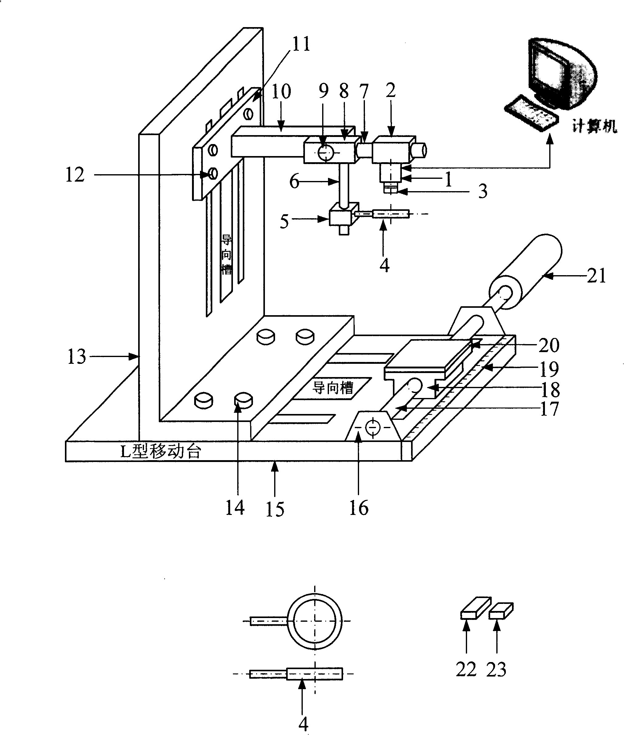
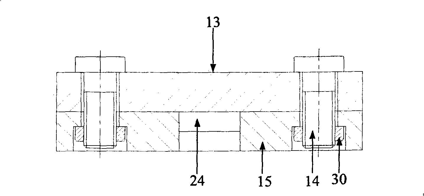
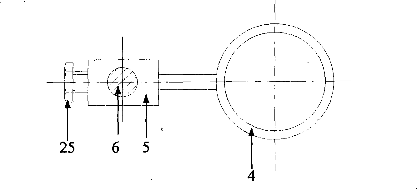
[0025] A measuring device for large-size parts based on machine vision, comprising a base 15 and large and small calibration blocks 22, 23. The length ratio of the large calibration block 22 and the small calibration block 23 is 3:2~2:1, In this embodiment, you can choose 3:2, 1.8:1 or 2:1. An L-shaped mobile station 13 is slidably connected to the base 15 and a support rod 10 is slidably connected to the vertical arm of the L-shaped mobile station 13. The sliding direction of the L-shaped mobile platform 13 is perpendicular to the sliding direction of the support rod 10. A rotating block 8 is rotatably connected to the support rod 10, and the rotational motion plane of the rotating block 8 is located between the sliding direction of the L-shaped mobile platform 13 and the support rod 10. The plane determined by the sliding direction is parallel, the camera support plate 2 is rotatably connected to the horizontal axis 7 of the rotating block 8, and the rotation motion plane of the...


PUM


Abstract

A large size element measuring device based on the machine vision comprises a chassis, a large calibration block and a small calibration block, wherein the length ratio of the large calibration block and the small calibration block is 3:2-2:1, an L-shaped mobile station is connected on the chassis in a sliding way, a support bar is connected on the vertical arm of the L-shaped mobile station in a sliding way, and the sliding direction of the L-shaped mobile station is perpendicular to the sliding direction of the support bar, a rotary block is rotatably connected on the support bar, and the rotational motion plane of the rotary block is perpendicular to a plane which is decided by the sliding direction of the L-shaped mobile station and the sliding direction of the support bar, a camera support plate is rotatably connected on the rotary block, and the rotational motion plane of the camera support plate is perpendicular to a plane which is decided by the sliding direction of the L-shaped mobile station and the sliding direction of the support bar, a camera is arranged on the camera support plate, a translation device is arranged on the chassis, a white background plate is arranged on the translation device, and is located under the camera, and a steel rule for observing the movement distance of a tray is arranged on the chassis.

Description

Technical field [0001] The invention belongs to the technical field of optical measurement, and relates to a vision measuring device for obtaining large-sized parts of the part size by using machine vision. Background technique [0002] There are three main channels for humans to transmit information: language, text and images. From the perspective of information theory, "images" contain the largest and richest amount of information. More than 70% of the external information obtained by humans comes from the eyes. In many occasions, there is no other form that is richer and more real than the information conveyed by images. In the past 20 years, a large number of scholars have studied the use of computers instead of humans to automatically process a large amount of "image" information, solving problems that cannot be recognized by human physiological organs, thereby partially replacing human brainwork, which makes image processing and analysis technology an interdisciplinary Cutt...

Claims


Application Information

Patent Timeline
IPC IPC(8): G01B11/00
Inventor 张志胜何博侠刘国良史金飞
Owner SOUTHEAST UNIV
Learn More