
Operation apparatus for three-position switch

An operating device and three-position technology, which is applied in the direction of electric switches, contact operating parts, high-voltage/high-current switches, etc., to achieve the effect of simple switching operation and labor-saving maintenance operation

Active Publication Date: 2009-01-21
MITSUBISHI ELECTRIC CORP
View PDF1 Cites 1 Cited by
  • Summary
  • Abstract
  • Description
  • Claims
  • Application Information

AI Technical Summary

Problems solved by technology

By connecting the manual operation handle with a stopper and the motor shaft to one of the two operation shafts, when one of the two operation shafts is connected to the manual operation handle or the motor shaft, it can only be turned on Toggle operation between the open position and the off position
When another operating shaft is connected to the manual operating handle and the motor shaft, it can only be switched between the ground position and the disconnected position.

Method used


Image

  • Operation apparatus for three-position switch
  • Operation apparatus for three-position switch
  • Operation apparatus for three-position switch

Examples


Embodiment approach 1

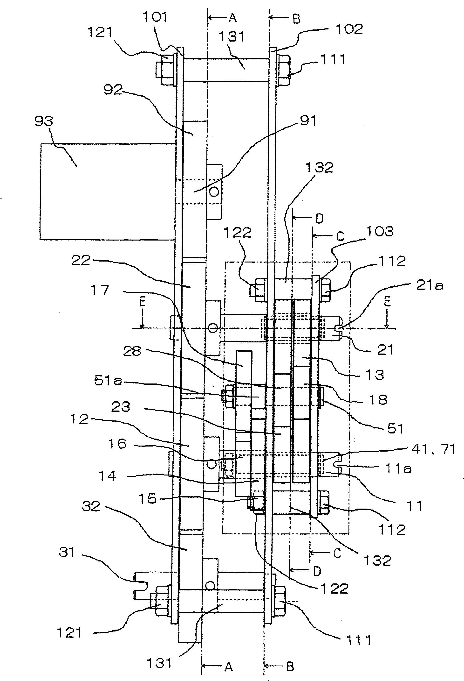
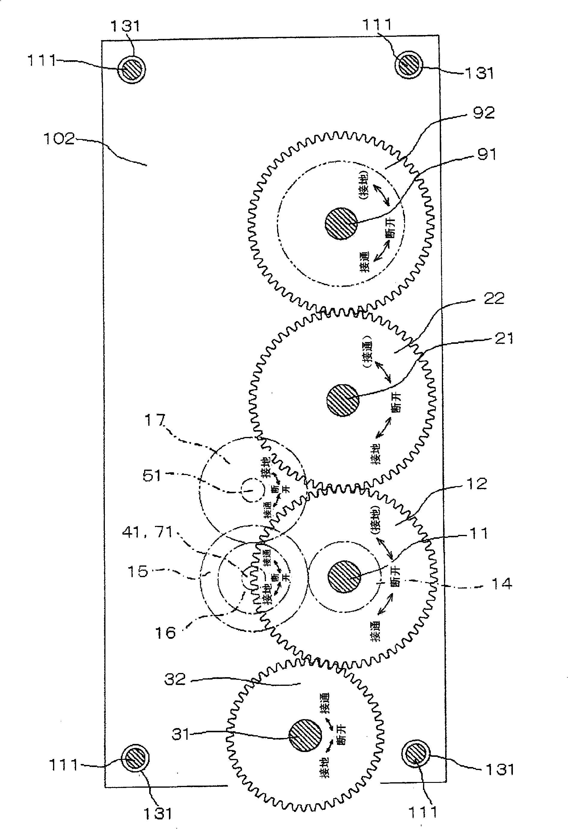
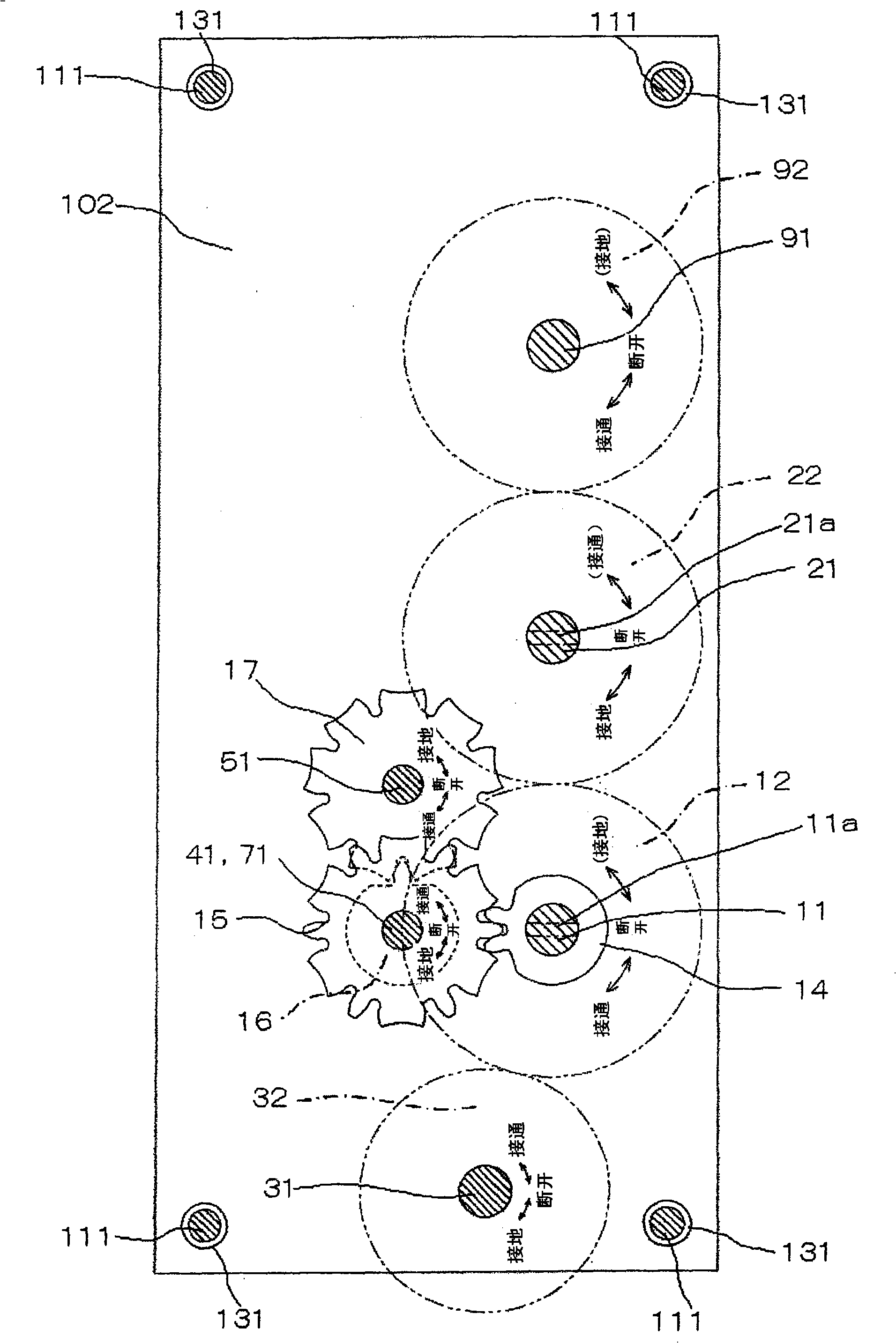
[0046] Hereinafter, Embodiment 1 of the present invention will be described in detail based on the drawings. figure 1 It is a side view showing a schematic configuration of the operating device for a three-position switch of the present invention. figure 2 yes figure 1 The A-A section diagram, image 3 yes figure 1 The B-B section diagram, Figure 4 yes figure 1 The E-E profile, Figure 5 is a side view showing the operating handle, Image 6 yes means figure 1 The C-C sectional view of the "disconnected" position in the middle, Figure 7 yes means figure 1 C-C sectional view of switching operation between "OFF" and "ON" positions in Figure 8 yes means figure 1 The C-C cross-sectional view of the "on" position in the middle, Figure 9 yes means figure 1 The D-D cross-sectional view of the "disconnected" position in the middle, Figure 10 yes means figure 1 D-D sectional view of switching operation between "disconnected" and "grounded" positions in Figure 11 ye...

Embodiment approach 2

[0089] Such as Figure 12 As shown, an engaging member 80 is embedded on the second operating shaft 21, and the engaging member 80 can slide freely between positions engaged with the first hook 13 and the second hook 23 along the axial direction. , and rotate integrally with the second operating shaft 21, in the state where the operating handle 84 is not connected to the second operating shaft 21, it is moved to a position where it can be engaged with the first hook 13 due to the action of the coil spring 83, And since the operating handle 84 is connected to the second operating shaft 21 and moves to a position where it can be engaged with the second hook 23 , the difference from the first embodiment is that there is no electromagnetic solenoid 81 .

[0090] The opening and closing operation between the "OFF" position and the "ON" position by remote operation in the above configuration will be described below. At this time, in the state where the operating handle 84 is not co...


PUM


Abstract

The invention relates to a three-position switch used operating device, which comprises a first operation shaft (11) and a second operation shaft (21) interlocked to each other driven by manual or electrical rotating; an output shaft (31) gaining a first and second position by the rotation of the first operation shaft (11) and gaining the second and third position by the rotation of the second operation shaft (21); a clutch component (80) capable of reciprocating on the second operation shaft (21) and moving to the first or second locking position selectively; a first hook object (13) capable of locking with the clutch component (80) on its first locking position when the output shaft (31) is at the first position to stop the rotation of the first operation shaft (11); and a second hook object (23) capable of locking with the clutch component (80) on its second locking position when the output shaft (31) is at the third position to stop the rotation of the second operation shaft (21).

Description

technical field [0001] The present invention relates to, for example, a three-position switch having three opening and closing positions such as an on position, an off position, and a grounding position. An operating device for a three-position switch consisting of a grounding switch in the grounding position. Background technique [0002] The conventional operating device for a three-position switch consists of an output shaft that takes three opening and closing positions corresponding to the three positions of the on position, the off position, and the ground position, and the required opening and closing position of the output shaft. Consists of 2 operation axes for driving operation. And, in this three-position switch operating device, from the viewpoint of implementing appropriate work, due to: (1) the operation of "from the off position to the on position" or "from the off position to the ground position" In the operation of "stop the rotation of the output shaft at...

Claims


Application Information

Patent Timeline
IPC IPC(8): H01H3/10H01H3/20H01H33/42
Inventor 森藤英二
Owner MITSUBISHI ELECTRIC CORP
Features
  • Generate Ideas
  • Intellectual Property
  • Life Sciences
  • Materials
  • Tech Scout
  • Unparalleled Data Quality
  • Higher Quality Content
  • 60% Fewer Hallucinations
Learn More