Airflow direction controllable air bag apparatus

A technology for controlling airflow and airbags, applied in transportation and packaging, pedestrian/occupant safety arrangement, vehicle safety arrangement, etc., can solve problems such as high cost, inconvenient installation and maintenance, occupant injury, etc., and achieve low cost, simple structure, and high protection. performance effect

Inactive Publication Date: 2009-01-28
JINZHOU JINHENG AUTOMOTIVE SAFETY SYST
View PDF0 Cites 4 Cited by
  • Summary
  • Abstract
  • Description
  • Claims
  • Application Information

AI Technical Summary

Problems solved by technology

If the occupant touches the airbag during the deployment phase of the airbag, the high impact force of the airbag can cause the occupant to be injured
Therefore, ordinary airbags cannot properly protect small occupants sitting forward and may even cause additional injuries
In order to solve this problem, intelligent airbags are produced to achieve appropriate protection for different occupants. Intelligent airbags need to rely on various occupant sensors to judge occupants, and then control the airbags to deploy in different states. Therefore, intelligent airbags The structure is complicated, the cost is expensive, the installation and maintenance are inconvenient, and there are special requirements for the body structure

Method used


Image

  • Airflow direction controllable air bag apparatus
  • Airflow direction controllable air bag apparatus
  • Airflow direction controllable air bag apparatus

Examples


Embodiment 1

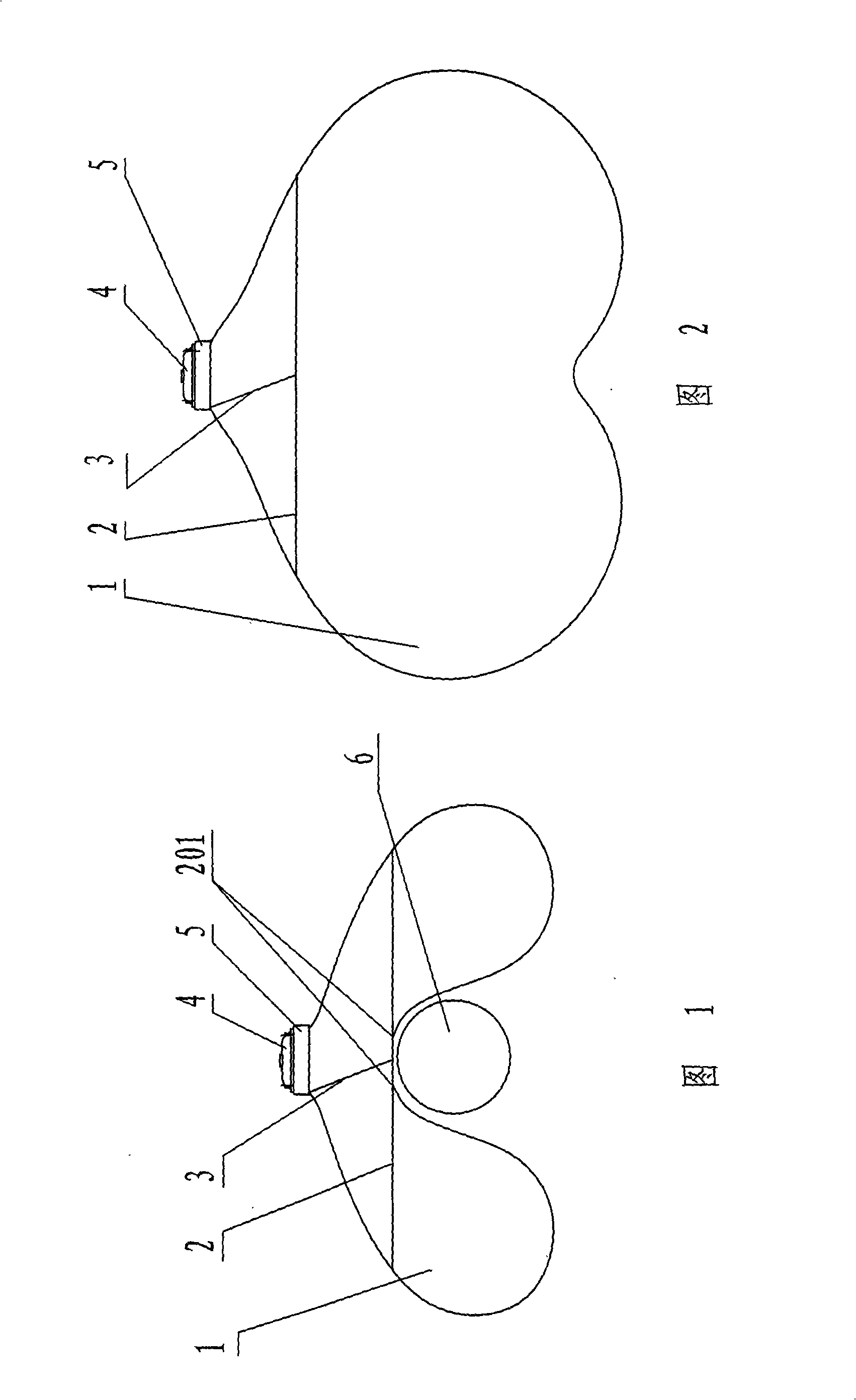
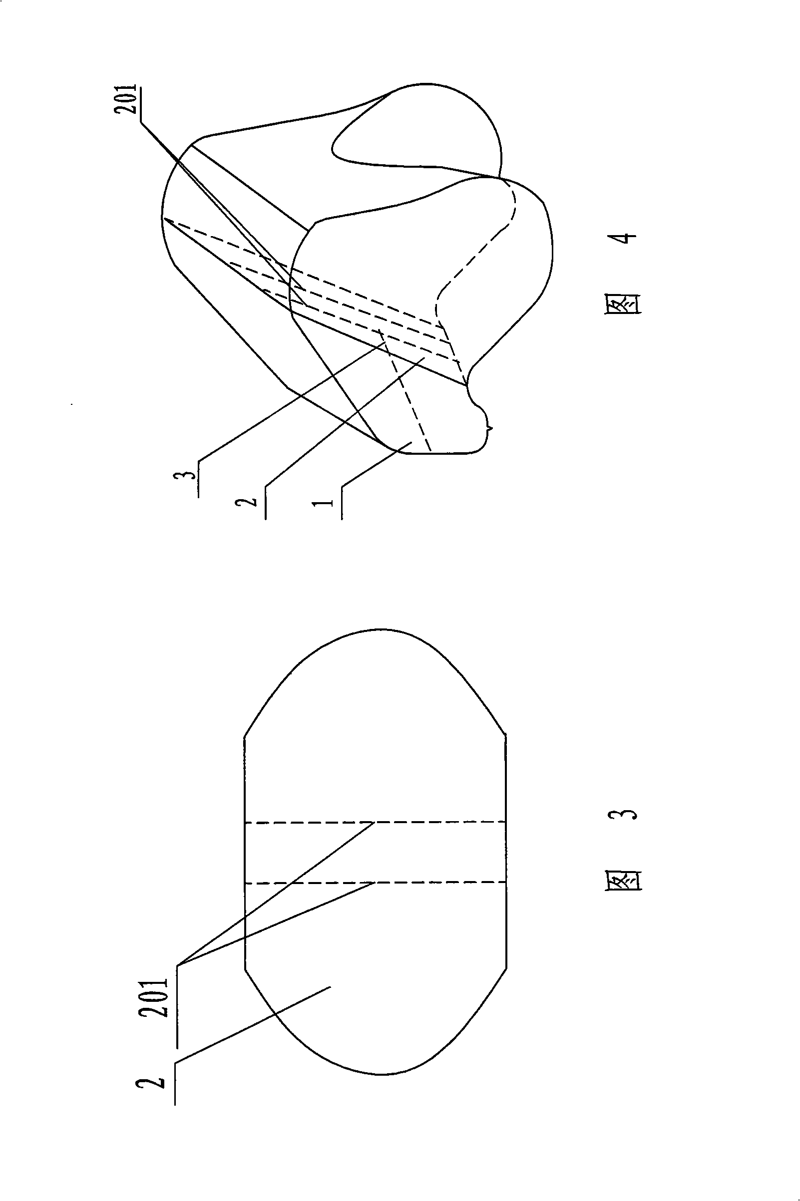
[0019] As shown in Fig. 1-Fig. 4, the present invention has a module support 5, is fixed with gas generator 4 and air bag 1 on module support 5, is provided with one or more drawstrings 3 in air bag 1, in air bag 1. The inner middle part is provided with a cloth piece 2 along the vertical direction (that is, the direction perpendicular to or nearly perpendicular to the direction of deployment of the air bag 1). The upper and lower edges of the cloth sheet 2 are respectively fixedly connected with the top and bottom of the air bag 1 by sewing thread. One end of the drawstring 3 is connected to the middle of the cloth sheet 2, and the other end of the drawstring 3 is fixed at the root of the air bag 1. The middle part of the front of the bag 1 is connected with the cloth piece 2 by a tearable sewing thread 201 (it can also be bonded by adhesive tape here).

[0020] When the vehicle collides, the gas generator 4 fills the air bag 1 with gas, and at the beginning of the air bag 1 ...

Embodiment 2

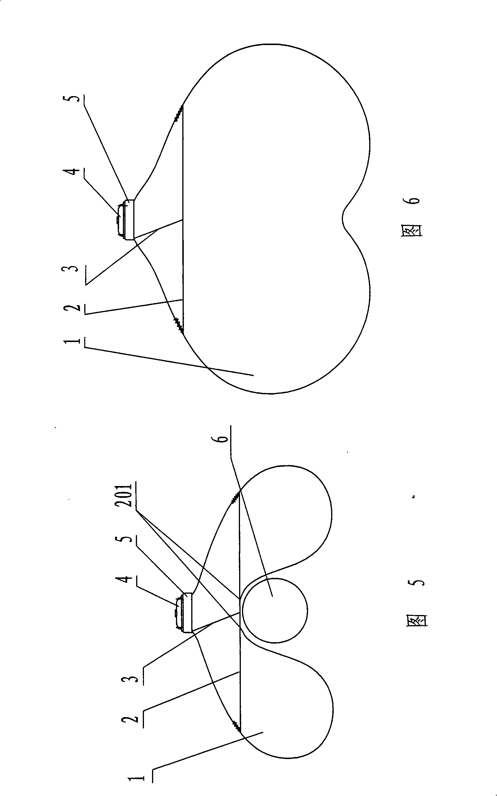
[0022] As shown in FIGS. 5-8 , the surrounding edges of the cloth sheet 2 are fixedly connected to the inner periphery of the air bag 1 through sewing threads, and vent holes 202 are respectively provided on both sides of the cloth sheet 2 . In the initial stage of air bag 1 deployment, the air flow flows into both sides of the front end of the air bag 1 through the exhaust holes 202 on both sides of the cloth sheet 2, and the others are the same as in the first embodiment.


PUM


Abstract

The invention relates to an air cell device that can control airflow direction, comprising a module bracket that is provided with an air generator and an air bag, the air bag is provided with a drawstring, a piece of cloth is arranged in the air bag along the vertical direction, one end of the drawstring is connected with the cloth, the other end is fixed on the root of the air bag, the middle of the front of the air bag is connected with the cloth by lacerable sewing thread or adhesive tape. The air cell device has the advantages as follows: the device has simple structure and can realize that two sides of the air bag are expanded firstly, and then the middle part is expanded, thus controlling the expanding speed of the middle in the front of the air bag, reducing momentary impact on a passenger in the expanding process of the air bag and avoiding the damage to the passenger in the initial stage of expanding; the device can provide protection for the passenger of normal sitting posture after complete expansion, the vehicle structure does not need to be changed, the device is compatible with the current safety air cell system, high protection property can be realized only by the current igniting circuit, and the device can satisfy higher and higher demands of consumers on passive safety .

Description

technical field [0001] The invention relates to a safety air bag device equipped on a car, in particular to an air bag device capable of controlling the direction of airflow. Background technique [0002] Ordinary airbags will release a lot of energy in an instant at the initial stage of deployment, and can produce high impact on the occupants. If an occupant touches the airbag during its deployment, the high impact force of the airbag can cause injury to the occupant. Therefore, ordinary airbags cannot properly protect small occupants who sit forward and may even cause additional injuries. In order to solve this problem, intelligent airbags are produced to achieve appropriate protection for different occupants. Intelligent airbags need to rely on various occupant sensors to judge occupants, and then control the airbags to deploy in different states. Therefore, intelligent airbags The structure is complicated, the cost is expensive, the installation and maintenance are inc...

Claims


Application Information

Patent Timeline
Patent Type & Authority Applications(China)
IPC IPC(8): B60R21/16B60R21/20B60R21/26
Inventor 陈静尹刚
Owner JINZHOU JINHENG AUTOMOTIVE SAFETY SYST
Why Eureka
Try Eureka