Method for implementing optical switch
A technology of optical switches and switching components, applied in the laser field, can solve the problems of not being suitable for Q-switching optical switches, high assembly process requirements, and non-adoption
- Summary
- Abstract
- Description
- Claims
- Application Information
AI Technical Summary
Problems solved by technology
Method used
Image

Examples
Embodiment 1
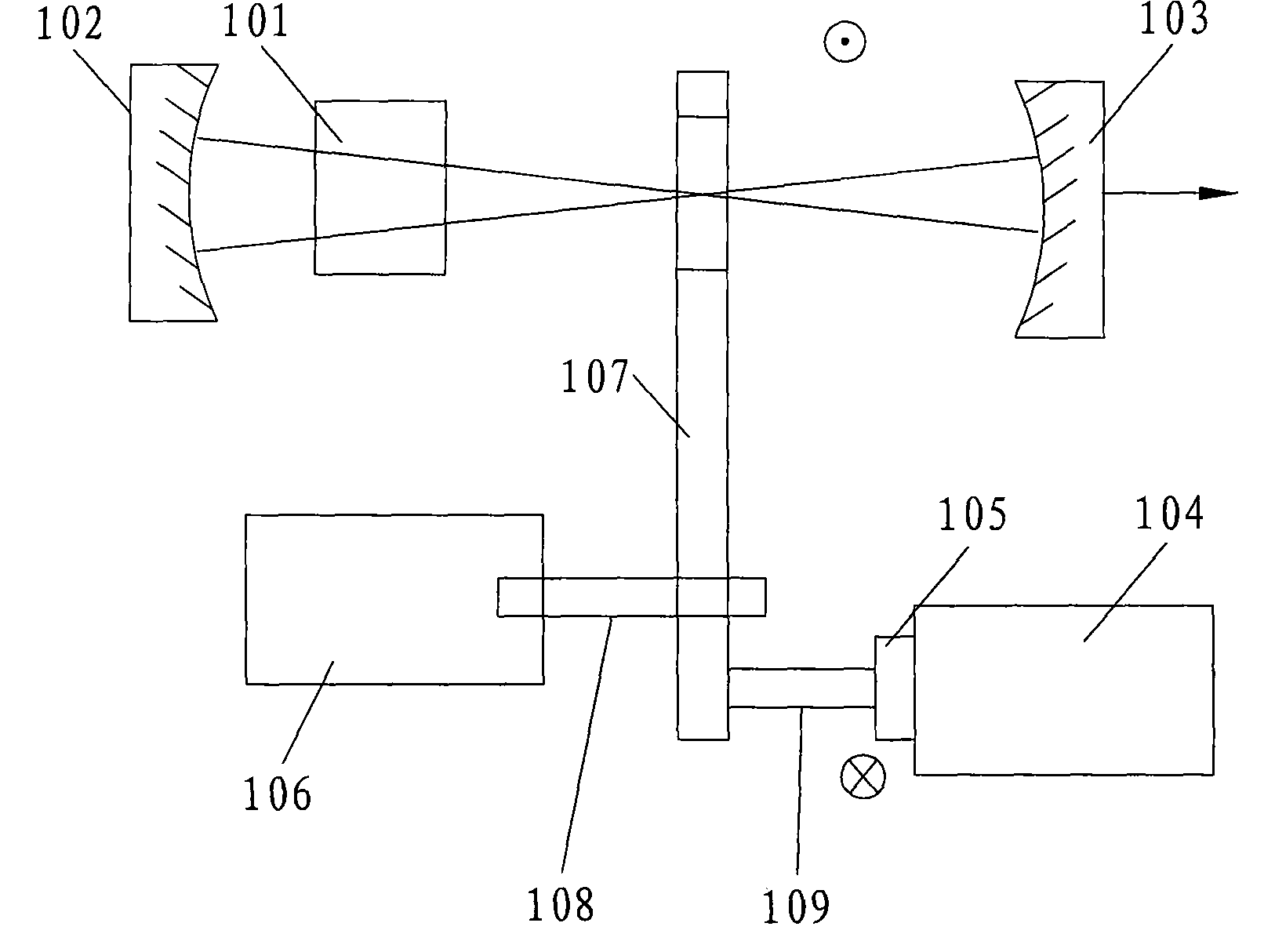
[0022] refer to figure 1 , is a schematic structural diagram of the first embodiment of the present invention. Wherein 102 and 103 are laser cavity mirrors, 101 is a laser gain medium, 104 is a relay, 107 is a movable rod, 106 is a fixed bracket with a rotating bearing, 108 is a connecting rod connecting the fixed bracket bearing and the movable arm, and 109 is The connecting rod, 105, is a connection block with a groove connecting the relay and the connecting rod 109.
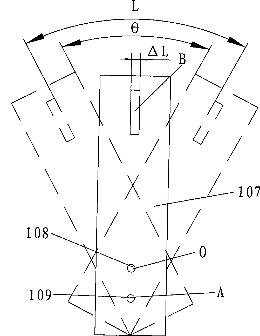
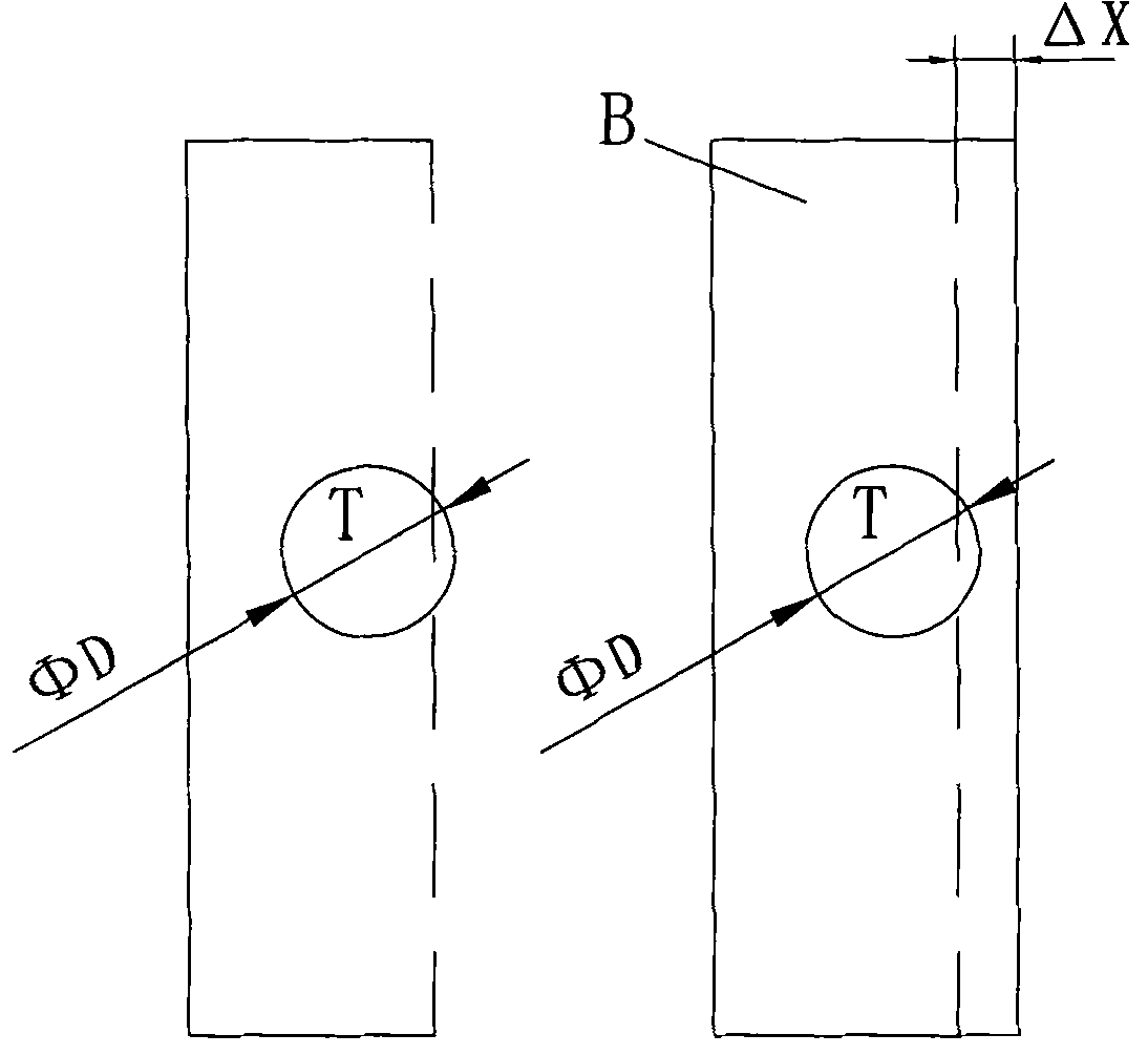
[0023] The position B of the movable rod 107 is a slit with a width of ΔL. The position of the slit is on the axis of the optical path of the laser.
[0024] refer to figure 2 and image 3 , the principle of the present invention is: in laser cavity mirror 102,103, in the laser cavity that laser gain medium 101 forms, insert movable rod 107, have slit B on the movable rod 107, movable rod 107 is formed by connecting rod 108 and band Rotational bearing support 106 is connected, and movable bar 107 can rot...
Embodiment 2
[0029] refer to Figure 5 It is a structural diagram of the second embodiment of the present invention. Figure 5 In the laser cavity, a passive Q-switching crystal 111 is added, the cavity mirror 102, the laser gain medium 101, another cavity mirror 103 and the passive Q-switching crystal 111 constitute a laser that directly generates a Q-switched output. Generally, its repetition frequency is 10K-100K, That is, the pulse time interval is 10μs-100μs.
[0030] The principle of the second embodiment of the present invention is to figure 1 The optical switch device in the first embodiment is placed outside the cavity as a single pulse selection device. If the slit is 50 μm, the single switching time of the relay 104 is 5 ms, and the repetition frequency of the pulse laser is 20K, that is, the pulse interval is 50 μs, then the movable rod is designed 107 single swing is 0.5mm, which can realize single pulse selection.
[0031] Image 6 It is a schematic diagram of an improved...
Embodiment 3
[0033] refer to Figure 8 , Figure 9 , is a schematic structural diagram of the third embodiment of the present invention. It adopts micro-mirror 211 to be fixed on one end of movable rod 107. When micro-mirror 211 turns to an appropriate position, cavity mirror 102, laser gain medium 101, and micro-mirror 211 generate laser oscillation. If micro-mirror 211 allows laser oscillation to deviate from is 30", and the micro-mirror 211 has a swing of 10° at a time. If the switching time of the relay is 0.5 ms, the Q switching time is about 500 ns, that is, it also reaches the same switching speed as the traditional mechanical Q switch.
[0034] The present invention adopts the relay commonly used in the circuit as the core to form the Q-switched laser driving element of the mechanical part, because the switching times of the relay can reach 10 7 -10 8 , the price is low, but compared with electro-optic Q-switching and acousto-optic Q-switching, its price is high, high voltage, a...
PUM
 Abstract
Description
Claims
Application Information