Cylinder material mixing device

A mixer and cylinder technology, applied in the direction of mixers, mixers with rotating containers, dissolution, etc., can solve the problems of increased length, high power consumption of motors, high energy consumption of equipment, etc., to achieve increased stability, enhanced rigidity, The effect of reducing motor power and equipment energy consumption

Inactive Publication Date: 2009-02-04
马铁林
View PDF0 Cites 4 Cited by
  • Summary
  • Abstract
  • Description
  • Claims
  • Application Information

AI Technical Summary

Problems solved by technology

[0003] However, because the cylinder structure of the existing cylinder mixer is generally a thin-walled structure, it must bear local support loads during work, and the strength of the cylinder limits the expansion of the diameter and length of the cylinder, thereby limiting the equipment. Large-scale
At the same time, the support structure of the cylinder generally adopts two or more sets of support rollers, and the cylinder relies on friction to drive the support wheels to rotate. Therefore, the power consumption of the motor is high, which makes the energy consumption of the whole machine high.
[0004] At present, my country's iron and steel industry is in the development stage of expanding scale, and the equipment of enterprises is developing in the direction of large-scale, especially the capacity of blast furnaces is constantly expanding, and the area of ​​corresponding sintering machines is also expanding. Therefore, the mixing equipment for sintering machines The capacity must also be expanded accordingly, and the larger the diameter of the mixer, the better the effect of material mixing and ball formation, but the structure of the existing cylindrical mixer limits the increase of its equipment capacity, and the equipment consumes a lot of energy

Method used


Image

  • Cylinder material mixing device
  • Cylinder material mixing device
  • Cylinder material mixing device

Examples


Embodiment Construction

[0019] In order to enable those skilled in the art to better understand the solution of the present invention, and to make the above-mentioned purpose, features and advantages of the present invention more obvious and comprehensible, the present invention will be further described in detail below in conjunction with the accompanying drawings and embodiments.

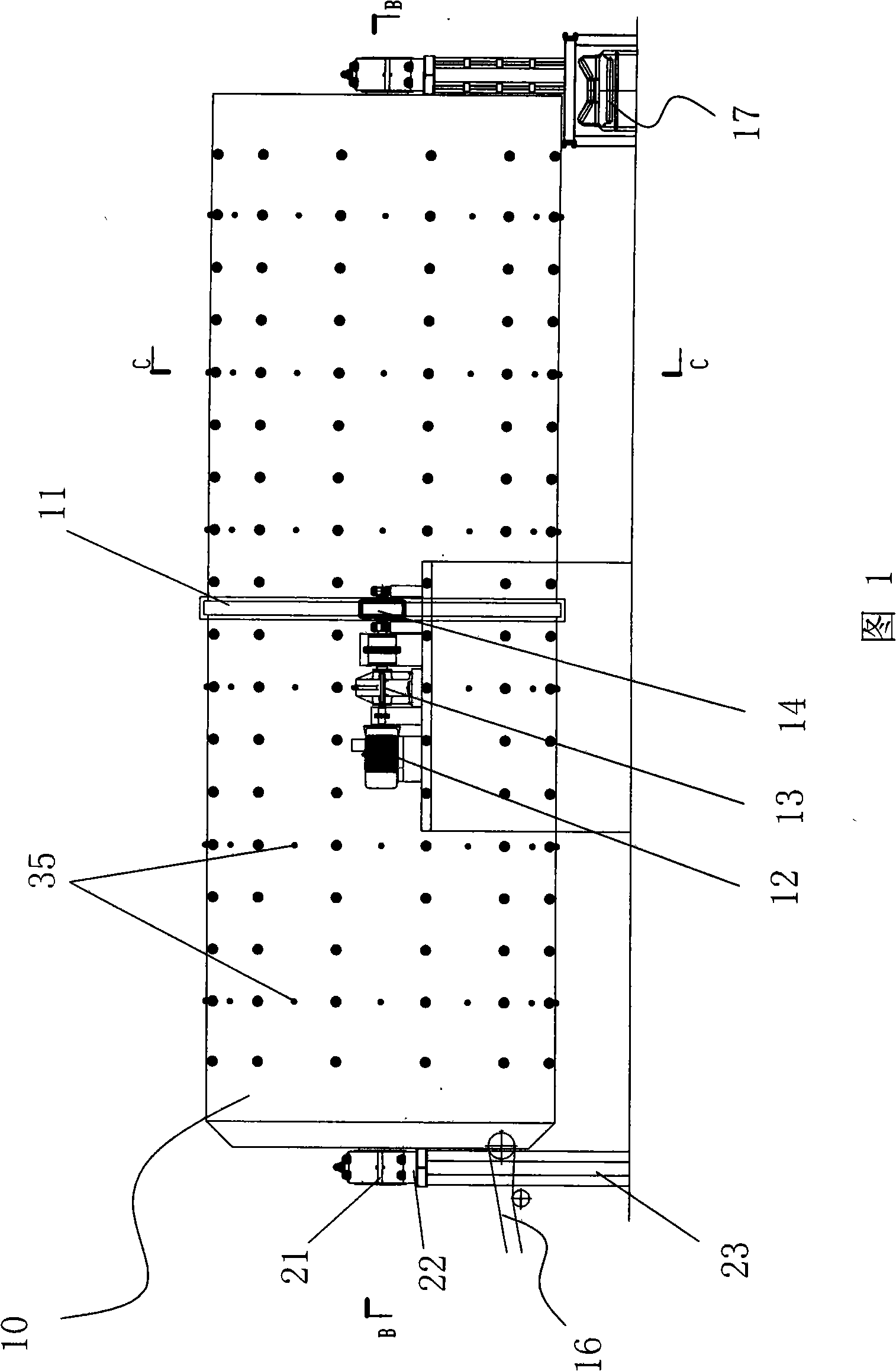
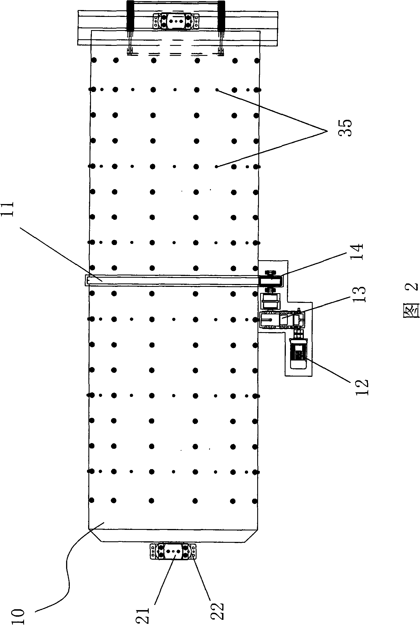
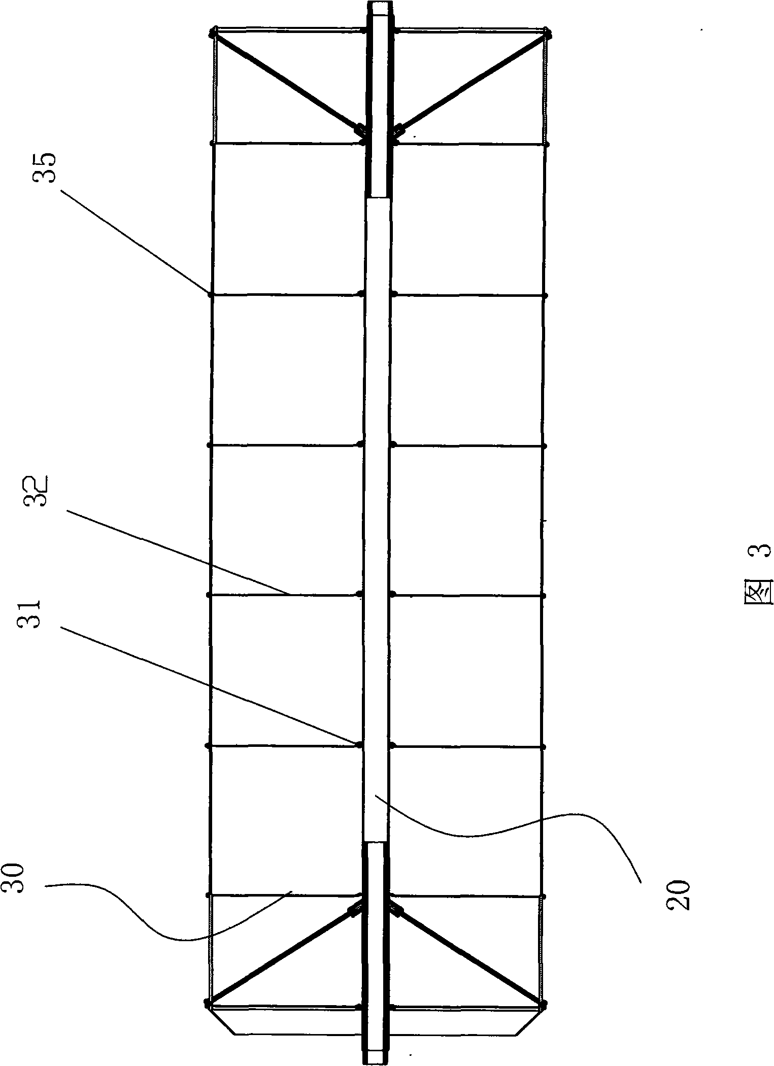
[0020] As shown in Figure 1, Figure 2, Figure 3, Figure 4 As shown, the embodiment of the cylindrical mixer provided by the present invention includes a cylinder 10 with openings at both ends, a ring gear 11 is hooped on the outer peripheral surface of the middle part of the cylinder 10, and a motor 12 arranged outside the cylinder 10 is passed through a deceleration The machine 13 is connected with the transmission gear 14, and the transmission gear 14 cooperates with the ring gear 11 to drive the cylinder body 10 to rotate; the cylinder body 10 is provided with a feeding belt conveyor 16 and a discharge belt conveyor 17...


PUM


Abstract

The invention discloses a cylindrical mixer which is used for solving the problem that the structure of existing cylindrical mixers can not be largely improved. The cylindrical mixer comprises a cylinder with openings at two ends, a ring gear is hooped on the outer circumference of the cylinder, a motor arranged outside the cylinder is connected with a transmission gear by a speed reducer, and the transmission gear is matched with the ring gear; the front and the rear of the cylinder are provided with a feeding conveyer and a discharge conveyer; a central shaft with two ends extending outside the cylinder is arranged inside the cylinder, the central shaft is connected with the cylinder by a collecting mechanism, the two ends of the central shaft are connected with a bearing seat by a bearing, and the bearing seat is fixed on a bracing structure. The cylindrical mixer is applicable to mixing iron making materials into balls.

Description

technical field [0001] The invention relates to a kind of equipment for mixing materials into balls, in particular to a cylinder mixing machine used in sintering plants of iron and steel enterprises. Background technique [0002] In the technological process of iron and steel enterprises, the concentrate powder, fuel, flux and other materials are usually mixed by a mixer, pelletized and then sintered, and the sintered ore is sent to the blast furnace for smelting; at present, in the existing various mixing Among the feeders, the cylinder mixer has the characteristics of stable operation, large single machine output, good mixing effect and good ball forming performance due to its circular symmetrical structure, so it is widely used in iron and steel enterprises. [0003] However, because the cylinder structure of the existing cylinder mixer is generally a thin-walled structure, it must bear local support loads during work, and the strength of the cylinder limits the expansion...

Claims


Application Information

Patent Timeline
Patent Type & Authority Applications(China)
IPC IPC(8): B01F9/02B01F29/60
Inventor 马铁林郭俊奎马杰韩顺兴吕文增牛永亮
Owner 马铁林
Why Eureka
Try Eureka