Laser indicator

A laser pointer and laser generator technology, applied in the field of laser applications, to achieve the effect of convenient use and light terminal device

Inactive Publication Date: 2009-02-04
SHANGHAI BRANCH FUZHOU GAOYI COMM CO LTD
View PDF0 Cites 6 Cited by
  • Summary
  • Abstract
  • Description
  • Claims
  • Application Information

AI Technical Summary

Problems solved by technology

At present, most of the laser pointers used are cylindrical pen-shaped structures, with a certain weight, and most of them need to be operated by hand.

Method used


Image

  • Laser indicator
  • Laser indicator
  • Laser indicator

Examples


Embodiment approach 1

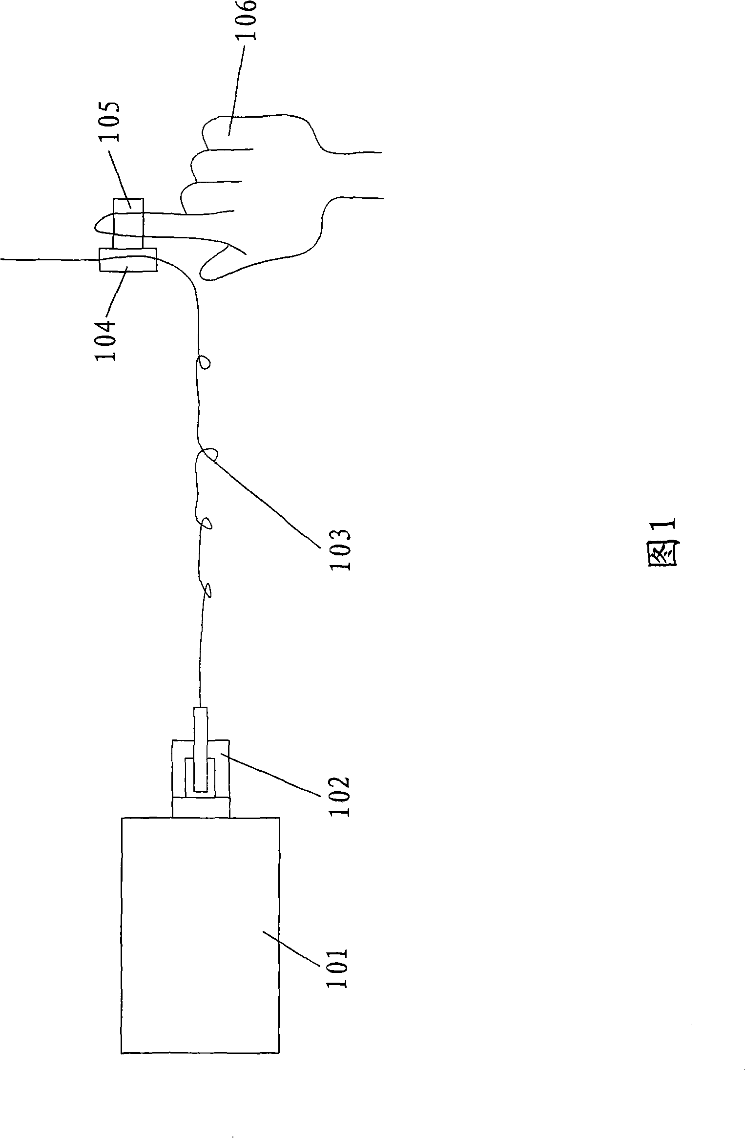
[0019] Embodiment 1: As shown in Figure 1, the initiator is a laser generator (101), the connection end is an optical fiber connection end (102), and the flexible cable is an optical fiber (103), The finger terminator is an optical fiber collimator (104); the laser light of the laser generator (101) is transmitted to the optical fiber (103) through the optical fiber connection end (102), and then the optical fiber collimator (104) outputs the laser light. Due to the flexibility of the fiber, it can be loosely fixed on the arm and connected to the laser on the body. Because the fiber collimator is very light and the fiber is very soft, it does not increase the burden on the hand and does not require conscious grasping, so it is very convenient to use.

Embodiment approach 2

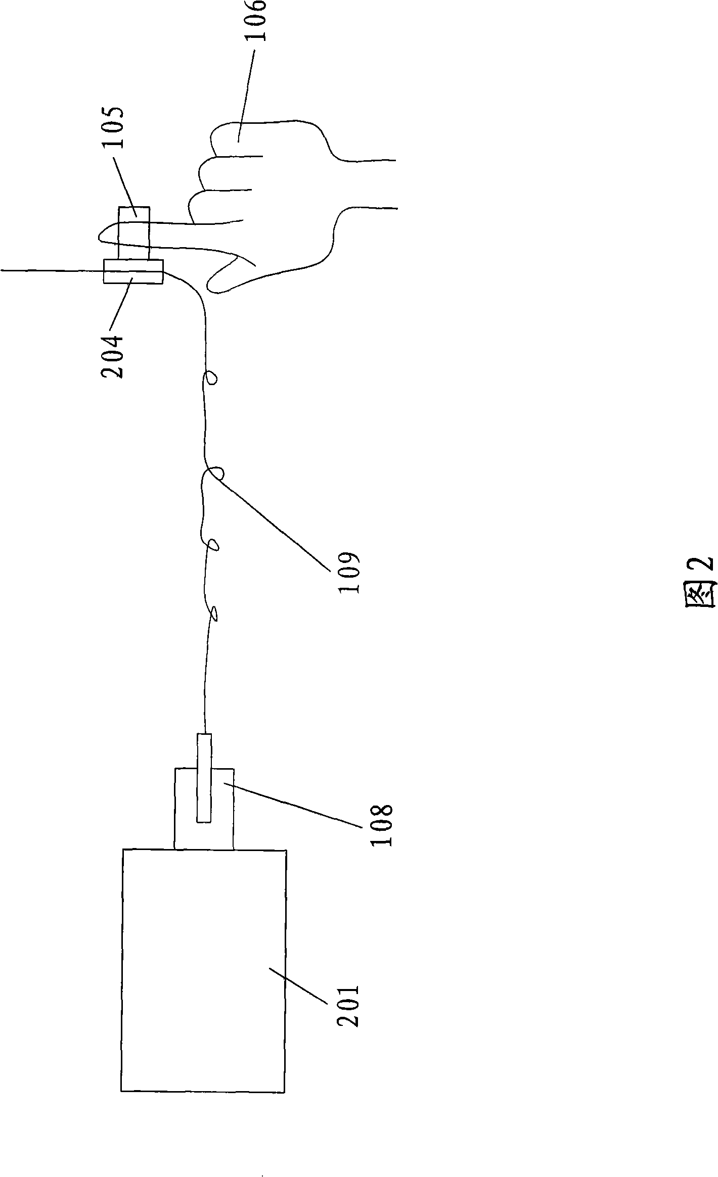
[0020] Embodiment 2: the initiator is a power supply (201), the connection terminal is a power supply connection terminal (108), the flexible cable is an electric wire (109), and the finger terminator is a miniature Laser (204); the current of the power supply (201) is transmitted to the electric wire (109) through the power supply connection terminal (108) and then drives the micro laser (204) to emit laser light. The micro laser (204) can be a semiconductor laser or a semiconductor pumping laser.

Embodiment approach 3

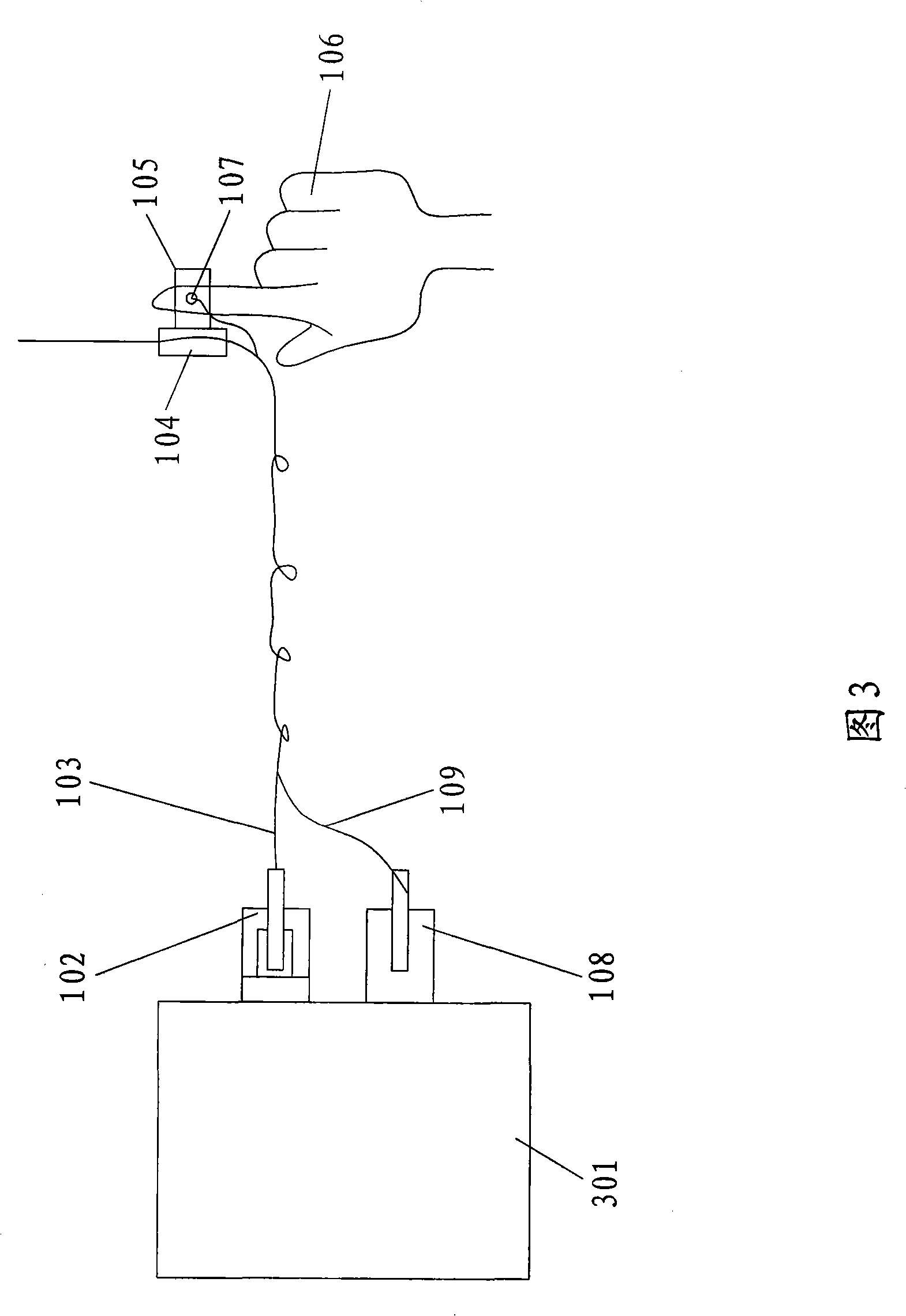
[0021] Embodiment 3: The initiator is a generating device (301) including a laser generator and a power supply, and the connection terminals are an optical fiber connection terminal (102) and a power supply connection terminal (108), and the Flexible cable is optical fiber (103) and electric wire (109), and described finger terminator is optical fiber collimator (105) and power switch (107); The laser of the laser generator (101) in generating device (301) After being transmitted to the optical fiber (103) through the optical fiber connection end (102), the laser is output by the optical fiber collimator (104), and whether the laser generator (101) emits laser light is controlled by the power switch (107) on the finger terminal. conduction. Easier to control since the laser switch is placed on the ring.

[0022] Further, the said finger fixing device is a ring cover, a glove, an arm cover or a fixing accessory fixed on other parts of the hand. The most recent embodiment of t...


PUM


Abstract

The invention relates to the application field of layer, in particular to a novel laser indicator. The laser indicator of the invention at least includes an initial device, a connection terminal, a flexible cable, a finger terminal device and a finger fixing device. The connection terminal is arranged on the initial device and is connected to the finger terminal device by the flexible cable; the finger terminal device is arranged on the finger fixing device. The finger fixing device is a ring sleeve, a glove, an arm sleeve or fixing fittings fixed on the other part of a hand. The laser indicator of the invention can be applied to the field of meeting teaching, laser indication of a traffic police, the laser indication of a solider on a battlefield, stage showing, entertainment, field glare weapon, and the like. Therefore, the invention relates to a novel layer indicator distinguished from a normal laser indicator; the terminal device is very light, can be better fixed with the finger and the arm and is very conveniently used.

Description

technical field [0001] The invention relates to the field of laser applications, in particular to a novel laser pointer. Background technique [0002] At present, when a presentation is to be made at a conference or a lecture, the lecturer no longer uses the past indicator stick for indication, but uses a laser pointer for indication, which can indicate a relatively long distance. The laser pointer can not only be used for conference teaching laser pointer, but also can be used in traffic command and police laser pointer, laser writing pen, entertainment and other fields. At present, most of the laser pointers used are in the shape of a cylindrical pen with a certain weight, and most of them need to be operated by hand. Contents of the invention [0003] In view of the above problems, the present invention proposes a new structure to change the traditional way of use. [0004] To achieve the above object, the present invention adopts the following technical solutions: ...

Claims


Application Information

Patent Timeline
IPC IPC(8): F21S9/02F21V21/08F21V23/00F21V23/06F21V8/00F21V23/04G09B17/02
Inventor 吴砺孙朝阳凌吉武杨建阳陈卫民
Owner SHANGHAI BRANCH FUZHOU GAOYI COMM CO LTD
Why Eureka
Try Eureka