Super-resolution compound shade differential confocal measuring device and method
A measuring device and differential confocal technology, applied in the field of ultra-precision measurement, can solve the problems of high installation and adjustment requirements, difficult processing, and inability to make corrections, achieve a large axial response range, facilitate engineering applications, and suppress common mode. the effect of interference
Inactive Publication Date: 2010-08-25
HARBIN INST OF TECH
View PDF0 Cites 0 Cited by
- Summary
- Abstract
- Description
- Claims
- Application Information
AI Technical Summary
Problems solved by technology
After the system is integrated, the overlapping position of the linear interval is fixed and cannot be corrected
Considering the influence of component manufacturing errors and system assembly and adjustment errors, in the disclosed multi-color super-resolution differential confocal measurement system, the precise control of the position of the overlapping area in the linear working area has the disadvantages of difficult processing and high requirements for assembly and adjustment.
Method used
View moreImage
Smart ImageViewing Examples
Examples
Embodiment Construction
Login to View More PUM
 Abstract
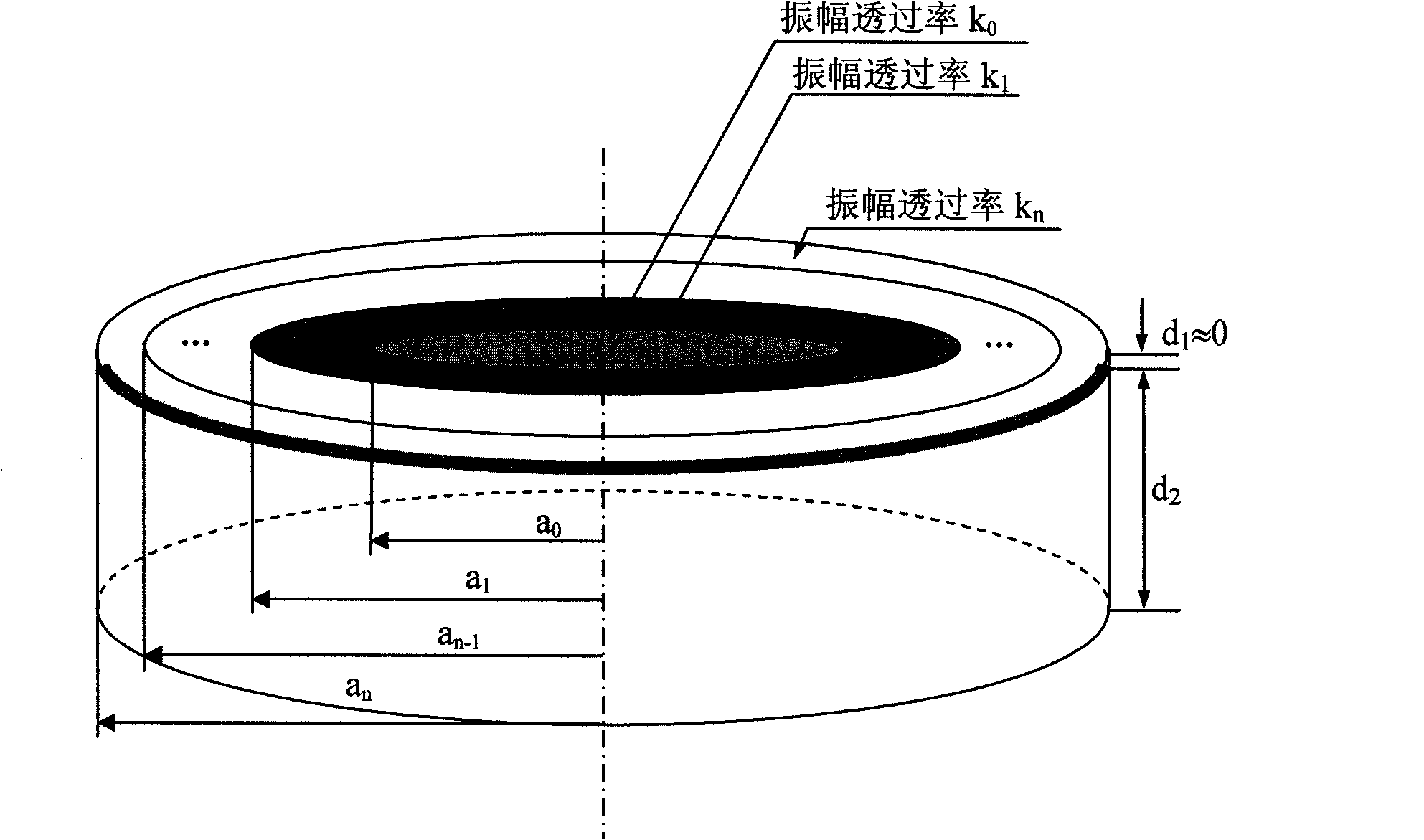
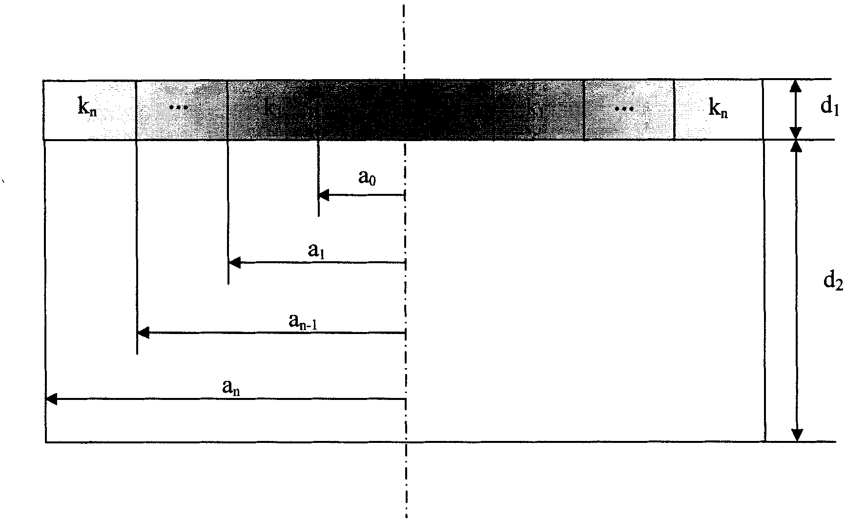
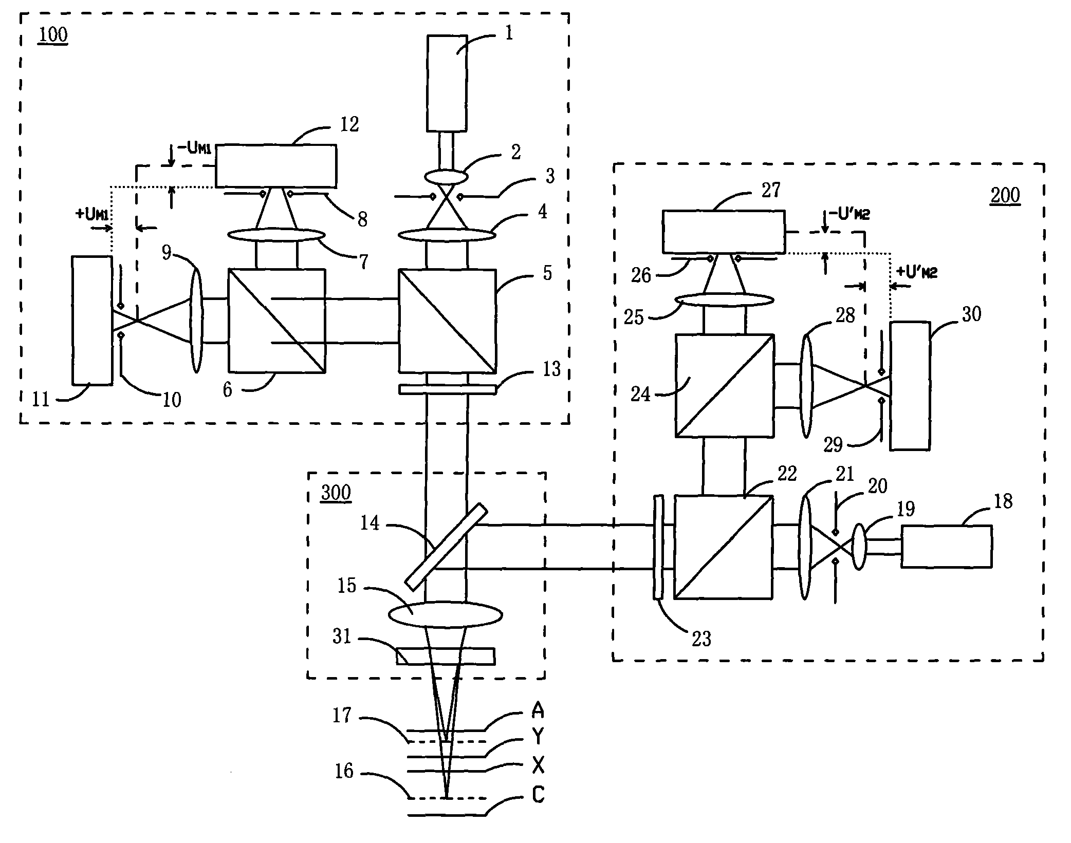
The present invention discloses a super-resolution secondary-color differential confocal measurement method, which comprises the steps that a first differential confocal measuring device, a paralleling flat-plate correction color difference super-resolution measuring head and a computer device are provided; the thickness of the base of a super-resolution filter flat plate is precisely corrected, and the plane position adjustment of the two light beam is realized, so that the position difference of the two focus plane is equal to the sum of half of the linear measurement zone of the first differential confocal measuring device and half of the linear measuring zone of the second differential confocal measuring device. The present invention also provides a super-resolution secondary-color differential confocal measuring device. The device and the method have the advantages that on the premise of the technical advantage that the known secondary-color super-resolution differential confocalmeasurement technology has two independent dual-polarity tracing linearity areas, and the axial responding measuring range is maximum, so that the common mode interference can be prevented, the transverse resolution of the system is improved.
Description
technical field The invention belongs to the field of ultra-precision measurement, and is an ultra-precise non-contact measuring device for measuring three-dimensional microstructures, microsteps, microgroove line width, depth and surface shape in microstructured optical elements, microstructured mechanical elements, and integrated circuit elements. measuring device. Background technique Super-resolution filtering technology is an optical filtering technology that obtains a smaller main lobe spot than the Airy disk by changing the amplitude transmittance distribution and phase distribution of the objective pupil and using the interference of coherent light. In the confocal measurement system, under the action of the confocal pinhole, the measurement resolution is improved at the expense of the field of view. Among the known super-resolution filtering technologies, the main technical approaches to realize optical filtering include amplitude filtering, phase filtering, comple...
Claims
Login to View More Application Information
Patent Timeline
 Patent Type & Authority Patents(China)
IPC IPC(8): G01B11/00G01B11/02G01B11/22G01B11/24
Inventor 刘俭谭久彬
Owner HARBIN INST OF TECH
Features
- R&D
- Intellectual Property
- Life Sciences
- Materials
- Tech Scout
- Unparalleled Data Quality
- Higher Quality Content
- 60% Fewer Hallucinations
Learn More Browse by: Latest US Patents, China's latest patents, Technical Efficacy Thesaurus, Application Domain, Technology Topic, Popular Technical Reports.
© 2025 PatSnap. All rights reserved.Legal|Privacy policy|Modern Slavery Act Transparency Statement|Sitemap|About US| Contact US: help@patsnap.com


