Interlace removing method, apparatus and system

A technology for deinterlacing and sending devices, which is applied in the field of deinterlacing methods, devices and systems, and can solve the problems of insufficient image display effect and not being able to accommodate all scenes, etc., and achieve the effect of improving image display quality

Inactive Publication Date: 2010-07-07
HUAWEI TECH CO LTD
View PDF0 Cites 0 Cited by
  • Summary
  • Abstract
  • Description
  • Claims
  • Application Information

AI Technical Summary

Problems solved by technology

[0004] Although de-interlacing can be achieved by using the above method, in the process of realizing the present invention, the inventors found that the method has at least the following defects: since all frames are de-interlaced using the same processing method, the scenes of different frames May be different, so not all scenarios, the image display is not good enough

Method used


Image

  • Interlace removing method, apparatus and system
  • Interlace removing method, apparatus and system
  • Interlace removing method, apparatus and system

Examples


Embodiment Construction

[0025] The following will clearly and completely describe the technical solutions in the embodiments of the present invention with reference to the accompanying drawings in the embodiments of the present invention. Obviously, the described embodiments are only some, not all, embodiments of the present invention. Based on the embodiments of the present invention, all other embodiments obtained by persons of ordinary skill in the art without creative efforts fall within the protection scope of the present invention.

[0026] In order to make the object, technical solution, and advantages of the present invention clearer, the present invention will be further described in detail below with reference to the accompanying drawings and examples.

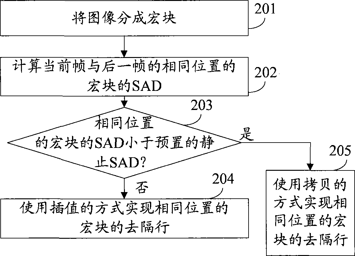
[0027] figure 2 The process of Embodiment 1 of the deinterlacing method provided by the embodiment of the present invention is described, including:

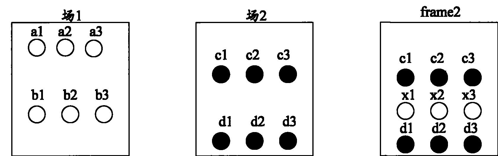
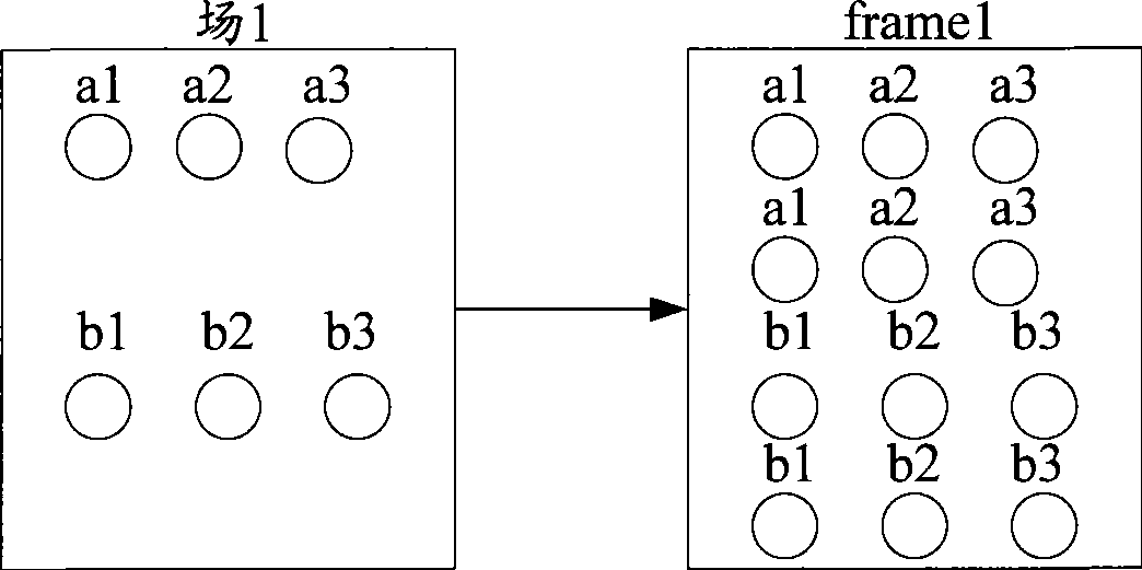
[0028] Step 201, dividing the image into macroblocks;

[0029] When an image is divide...


PUM


Abstract

The invention relates to the display technology, and discloses a de-interlacing method, a de-interlacing device and a de-interlacing system, wherein the de-interlacing method comprises that an absolute error sum of macro blocks at an identical position of a current frame and a next frame is calculated; when the absolute error sum of the macro blocks at the identical position is smaller than a preset stationary absolute error sum, the de-interlacing of the macro blocks at the identical position is realized by using the copying mode. By using, the technical proposal provided by the embodiments of the invention can adopt different processing modes to different frames to carry out de-interlacing, and can combine different scenes to enhance the display quality of an image.

Description

technical field [0001] The present invention relates to display technology, in particular to a deinterlacing method, device and system. Background technique [0002] When television broadcasting was first carried out, the progressive scan television system was adopted, but the definition was not enough. Later, when people wanted to move movie programs to TV programs, they strongly felt that the definition of TV sets was not enough. For this reason, interlaced scanning TV sets were invented. Interlaced video takes advantage of the inherent response time of the human visual system to achieve the same experience as progressive scan television. However, interlaced scanning TV has a disadvantage, that is, when the contrast between the upper and lower lines of the image is very different, inter-line flicker (called inter-line flicker) occurs. To solve this shortcoming, TVs have begun to use progressive scanning. In order to be compatible with the video source of interlaced scann...

Claims


Application Information

Patent Timeline
Patent Type & Authority Patents(China)
IPC IPC(8): H04N7/01H04N5/44
Inventor 樊进国
Owner HUAWEI TECH CO LTD
Why Eureka
Try Eureka