Fluorescent light luminotron and its manufacturing method

A light-emitting tube and fluorescent technology, which is applied in the manufacture of tube/lamp screen, discharge tube/lamp, cold cathode manufacture, etc. , easy-to-manufacture effects

Inactive Publication Date: 2006-03-08
FUTABA CORPORATION
View PDF1 Cites 0 Cited by
  • Summary
  • Abstract
  • Description
  • Claims
  • Application Information

AI Technical Summary

Problems solved by technology

For this reason, it is very difficult to manufacture high-resolution display tubes using prior art fluorescent light-emitting tubes

Method used


Image

  • Fluorescent light luminotron and its manufacturing method
  • Fluorescent light luminotron and its manufacturing method
  • Fluorescent light luminotron and its manufacturing method

Examples


Embodiment Construction

[0031] now refer to Figures 1A to 5 , a graphic fluorescent display tube and a manufacturing method thereof according to a preferred embodiment of the present invention are described in detail. Like numbers denote like parts in the drawings.

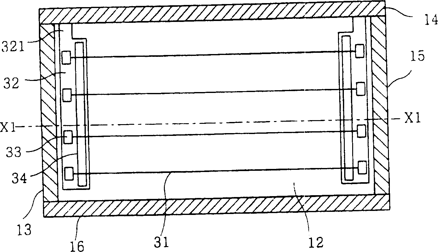
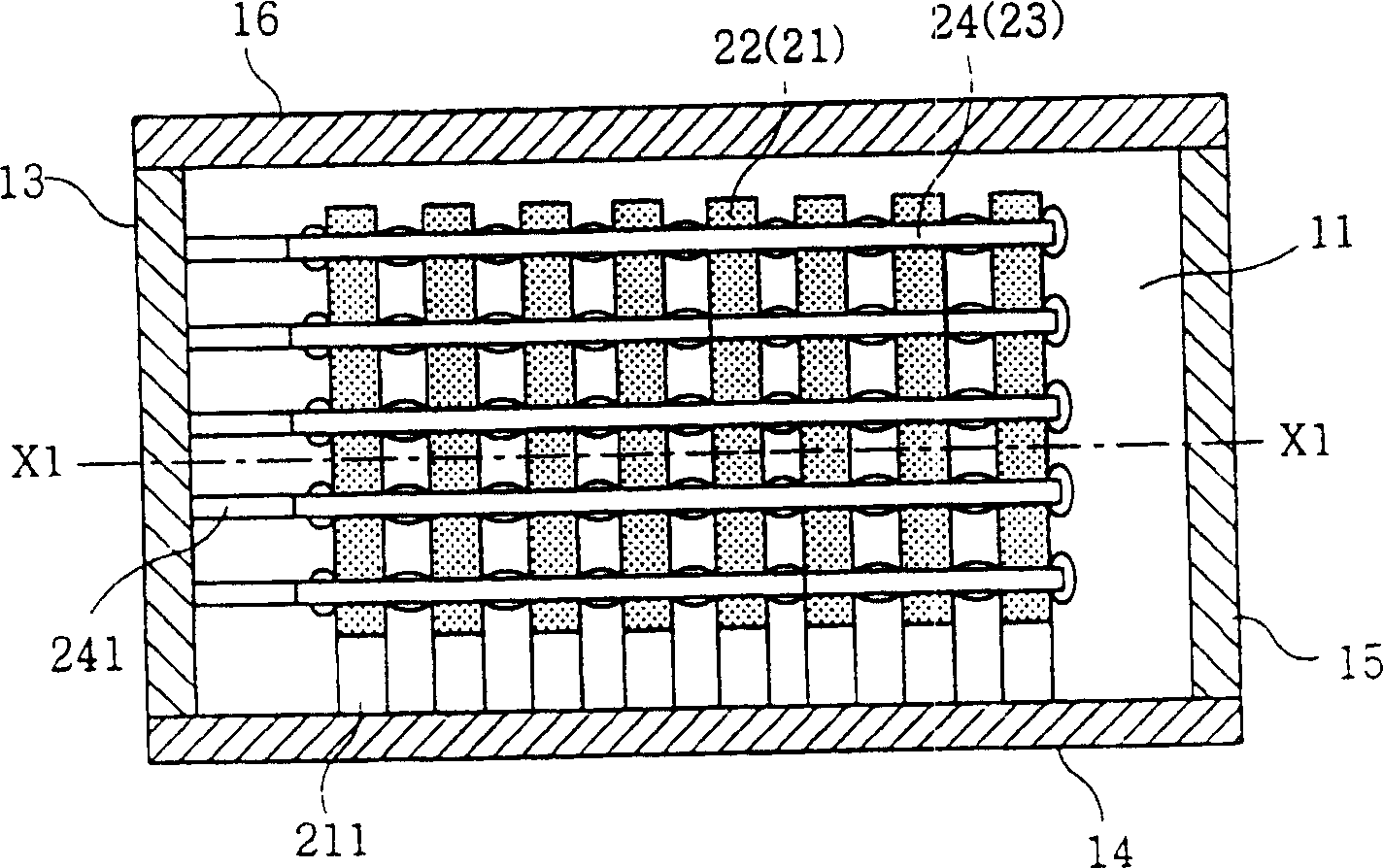
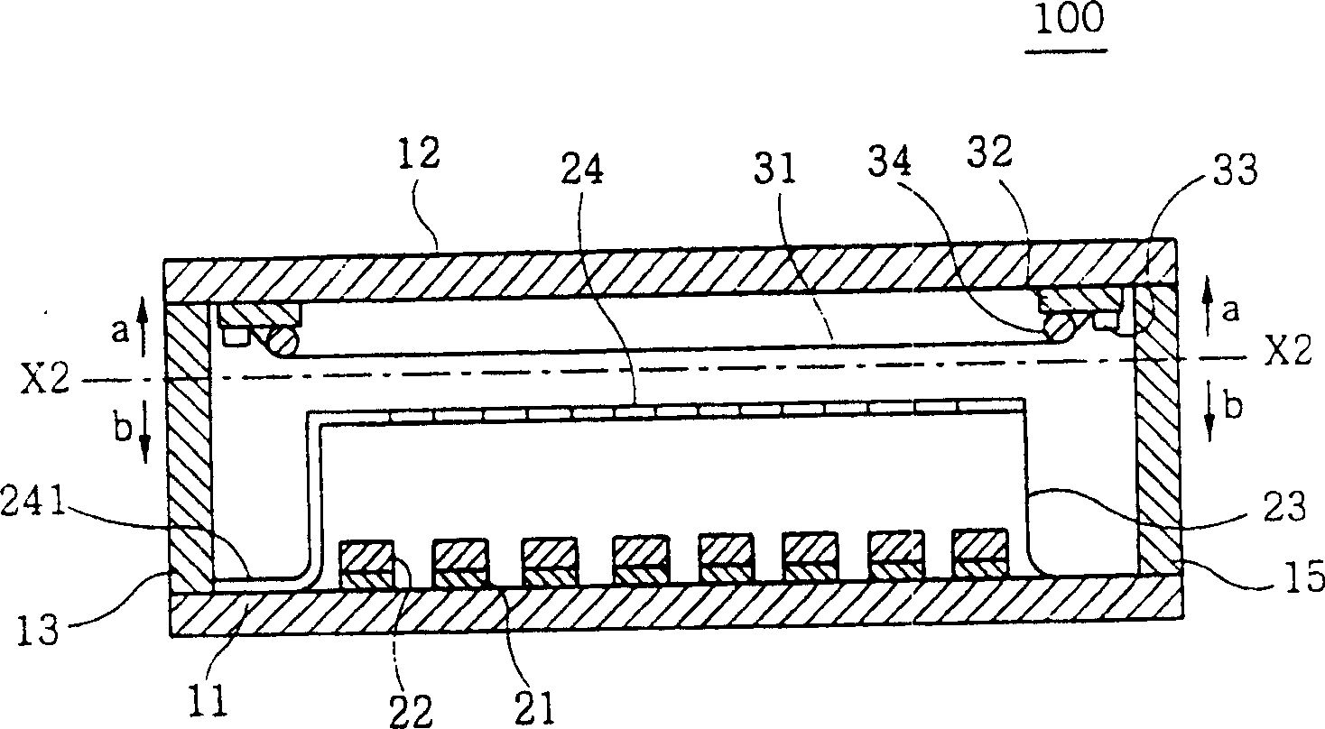
[0032] Figures 1A to 1C , Figure 2A and 2B are a plan view and a cross-sectional view, respectively, of a graphic fluorescent display tube 100 according to a first preferred embodiment of the present invention. Figure 1C is along Figure 1A and 1B The cross-sectional view made by the line "X1-X1"; Figure 1A and 1B are along Figure 1C A plan view taken along the line "X2-X2" in the direction of arrows "a" and "b"; Figure 2A show Figure 1B Partial enlarged view of Figure 2B shows along the Figure 2A The cross-sectional view made by the line "X3-X3" in;

[0033] The graphic fluorescent display tube 100 according to the first preferred embodiment of the present invention comprises side walls 13 to 16, an anode substrat...


PUM


Abstract

A fluorescent luminous device includes a substrate, a plurality of anode electrodes disposed directly on the substrate, fluorescent layers disposed on the anode electrodes, a multiplicity of separators disposed on the fluorescent layers and the substrate, grid electrodes respectively disposed on the separators to form a matrix structure, and an electron-emitting source spaced apart from the fluorescent layers for exciting a fluorescent substance of the fluorescent layers. The fluorescent layer is of a stripe pattern or an array of fluorescent dots. In the latter case, at least a part of each of two neighboring separators is located on one fluorescent dot.

Description

field of invention [0001] The present invention relates to a fluorescent light-emitting tube and a manufacturing method thereof, wherein the fluorescent light-emitting tube has an anode and a grid in a matrix form, and the grid is formed on an insulating partition. Background of the invention [0002] Figures 6A to 6C A graphic fluorescent display tube is shown, the tube being of the prior art fluorescent light emitting tube type, wherein Figure 6A shows its floor plan; Figure 6B is along Figure 6A The sectional view made by the line "Y1-Y1"; Figure 6C yes Figure 6B A magnified view of a portion of . [0003] The prior art graphic fluorescent display tube includes an anode substrate 51 made of glass, filaments 61 respectively serving as cathodes, a fixing member 62 for applying tension to the filament 61, a support member 63 for supporting the filament 61, an insulating layer 64, Anode 71 , fluorescent layer 72 , spacer 73 made of insulating material, metal layer ...

Claims


Application Information

Patent Timeline
Patent Type & Authority Patents(China)
IPC IPC(8): H01J31/15H01J9/04G09G3/10H01J9/18H01J9/20H01J9/227H01J9/24H01J29/02H01J29/30H01J29/46H01J29/82H01J31/12
CPCH01J9/185H01J29/467H01J31/126H01J29/028H01J9/20H01J31/15
Inventor 米泽祯久铃木博之饭田克俊小川行雄
Owner FUTABA CORPORATION
Why Eureka
Try Eureka