Feed apparatus of calender press

A technology of feeding device and roller press, applied in grain processing and other directions, can solve the problems of affecting the extrusion effect of the roller press, unable to adjust the load moment of the fixed roller, affecting the service life of the bearing, etc., to eliminate the leakage of the roller end phenomenon, the phenomenon of material leakage at the end of the roll is eliminated, and the effect of improving the extrusion effect

Inactive Publication Date: 2009-02-11
WUXI TIANSHAN CEMENT
View PDF0 Cites 9 Cited by
  • Summary
  • Abstract
  • Description
  • Claims
  • Application Information

AI Technical Summary

Problems solved by technology

[0005] Defects in the current feeding device of the roller press: 1. For the case where the material particles entering the roller press are small or the material particles change greatly, the material cannot form a sufficiently dense material column in the feeding device, so that it cannot ensure that the material enters the roller press. The material between the two rollers of the roller press is fully squeezed to form a cake
2. Since the hopper and the side baffle of the feeding device of the roller press are actually two separate parts, the side baffle is fixed on the bearing seat of the roller press and has a distance of about 10mm from the end faces of the two extrusion rollers of the roller press. In this way, the side baffles are often squeezed and rubbed by the leakage of the roller end, and are easily worn and deformed, which will eventually lead to greater leakage of the roller end. On the one hand, it will seriously affect the extrusion effect of the roller press, and on the other hand On the one hand, a large amount of material leakage at the end of the roller caused the J-shaped frameless seal ring of the large bearing of the roller press to wear too quickly and fail prematurely, resulting in dust entering the bearing and seriously affecting the service life of the bearing
3. The adjustment effect of the adjustment plate is very poor, and it is very laborious to adjust, and the load moment of the movable and fixed roller cannot be effectively adjusted according to the specific situation.

Method used


Image

  • Feed apparatus of calender press
  • Feed apparatus of calender press
  • Feed apparatus of calender press

Examples


Embodiment Construction

[0017] Below the present invention will be further described in conjunction with the embodiment in the accompanying drawing:

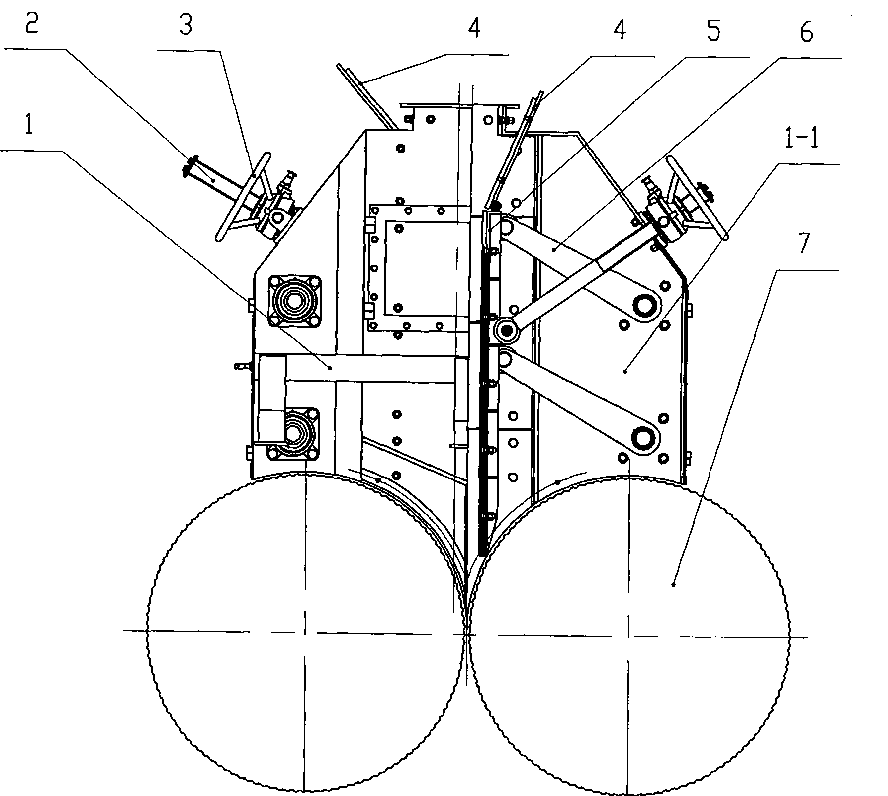
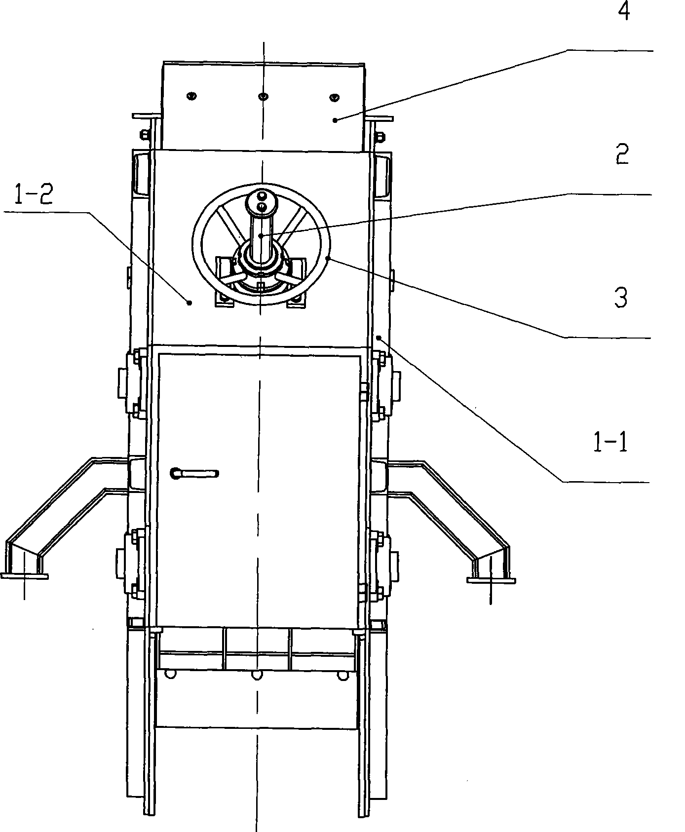
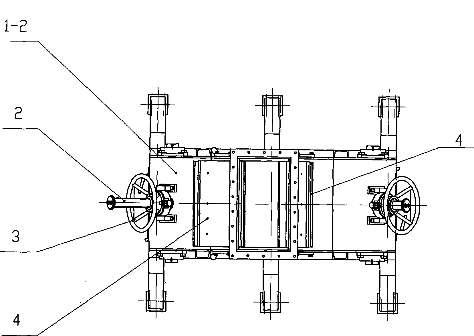
[0018] Such as Figure 1 ~ Figure 3 As shown, it includes a housing 1 (side wall panels 1-1, end wall panels 1-2), an adjusting screw 2, an adjusting mechanism 3, a retaining plate 4, an adjusting plate 5, a supporting mechanism 6, and the like.

[0019] The housing 1 of the present invention consists of two end wall panels 1-2 and two side wall panels 1-1 connected into one body by welding, and the hand wheel nut part support of the adjustment mechanism 3 is fixed on the housing end wall panel by bolts. One end of the upper and supporting mechanism 6 runs through the shaft and is fixed on the side wall plate 1-1 of the housing 1 through an outer spherical ball bearing with a square seat, and the other end is connected with the adjustment plate 5 through a hinged joint; the thread of the adjustment screw 2 Part of it is screwed with the internal threa...


PUM


Abstract

The invention relates to a feeding device of a roller press, which is characterized in that a hand wheel nut of an adjusting mechanism is fixed on an end sheathing by a screw; a shaft at one end of a supporting mechanism is fixed on a side sheathing of a shell body by a bearing; four steel plates of the shell body are connected as a whole by welding; the other end of the supporting mechanism is articulated with an adjusting plate; an adjusting screw of the adjusting mechanism is engaged with internal screw thread of the adjusting mechanism the other end of which is connected with the adjusting plate through a hinge; and a feed deflector is articulated with the adjusting plate. The feeding device of the roller press can well eliminate feed leakage at the roller end which is common in the existing roller press and the feed can be shaped into better feed cakes after being pressed with obviously improved pressing efficiency; the feeding device can also ensure that the feed of different particles can enter a squeeze roller with a convenient and flexible adjusting method and obvious effects; as the feed leaking at the roller end is eliminated, the wear of a J-shaped skeletonless sealing ring of the bearing of the squeezer roller is greatly reduced, which can prevent external dust from entering the bearing and prolong the service life of the bearing.

Description

technical field [0001] The invention relates to a feeding device of a roller press, in particular to an auxiliary device of a roller press, an important cement grinding equipment. Background technique [0002] The roller press is a kind of high-efficiency and energy-saving cement grinding equipment. It mainly relies on two squeeze rollers installed horizontally and synchronously rotating in opposite directions to press the sealing roller under the action of the extrusion force of several hundred tons or even thousands of tons provided by its hydraulic system. In the feeding device of the roller press, the mutually extruded materials that forcibly enter the extrusion rollers of the roller press under the action of the material pressure are crushed in a high-pressure material layer. The material that continuously enters the feeding device of the roller press through the silo is forced to move downward under the pressure generated by its own weight, and the extrusion force on t...

Claims


Application Information

Patent Timeline
Patent Type & Authority Applications(China)
IPC IPC(8): B02C4/28B02C23/02
Inventor 顾茂松
Owner WUXI TIANSHAN CEMENT
Why Eureka
Try Eureka