A sealing seat device for roll boxes of high-line finishing mills

A technology for sealing seats and finishing mills, which is applied to the sealing of engines, metal rolling mill stands, metal rolling stands, etc., which can solve the problems of increasing maintenance costs, increasing wear of double lip seals and oil flingers, and polluting lubricating oil System and other issues, to achieve the effect of increasing service life, reducing processing difficulty, and reducing production costs

Active Publication Date: 2017-11-03
MAANSHAN IRON & STEEL CO LTD
View PDF4 Cites 0 Cited by
  • Summary
  • Abstract
  • Description
  • Claims
  • Application Information

AI Technical Summary

Problems solved by technology

There is high-pressure roller ring cooling water on the outer side of the seal seat. The cooling water brought up by the upper and lower roller rings during the rolling process washes the seal seat, forming concentrated pits on the surface of the seal seat. During the roll gap adjustment process, When the oil slinger is adjusted to the pit, the cooling water with high pressure will follow the gap between the oil slinger and the pit, bring iron filings into the sealing cavity, and block the double lip seal and the oil slinger In between, the wear of the double lip seal and the flinger ring is increased, and it becomes invalid, pollutes the lubricating oil system and damages the oil film bearing, and increases the maintenance cost

Method used


Image

  • A sealing seat device for roll boxes of high-line finishing mills
  • A sealing seat device for roll boxes of high-line finishing mills
  • A sealing seat device for roll boxes of high-line finishing mills

Examples


Embodiment Construction

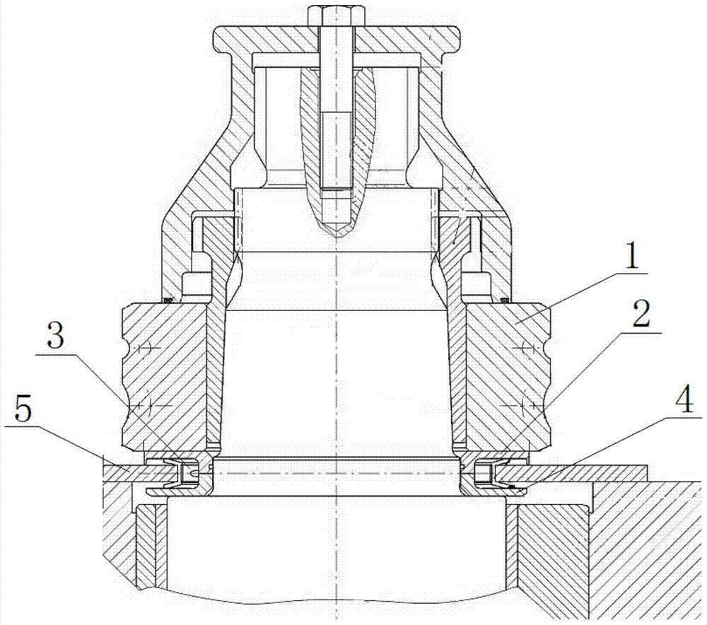
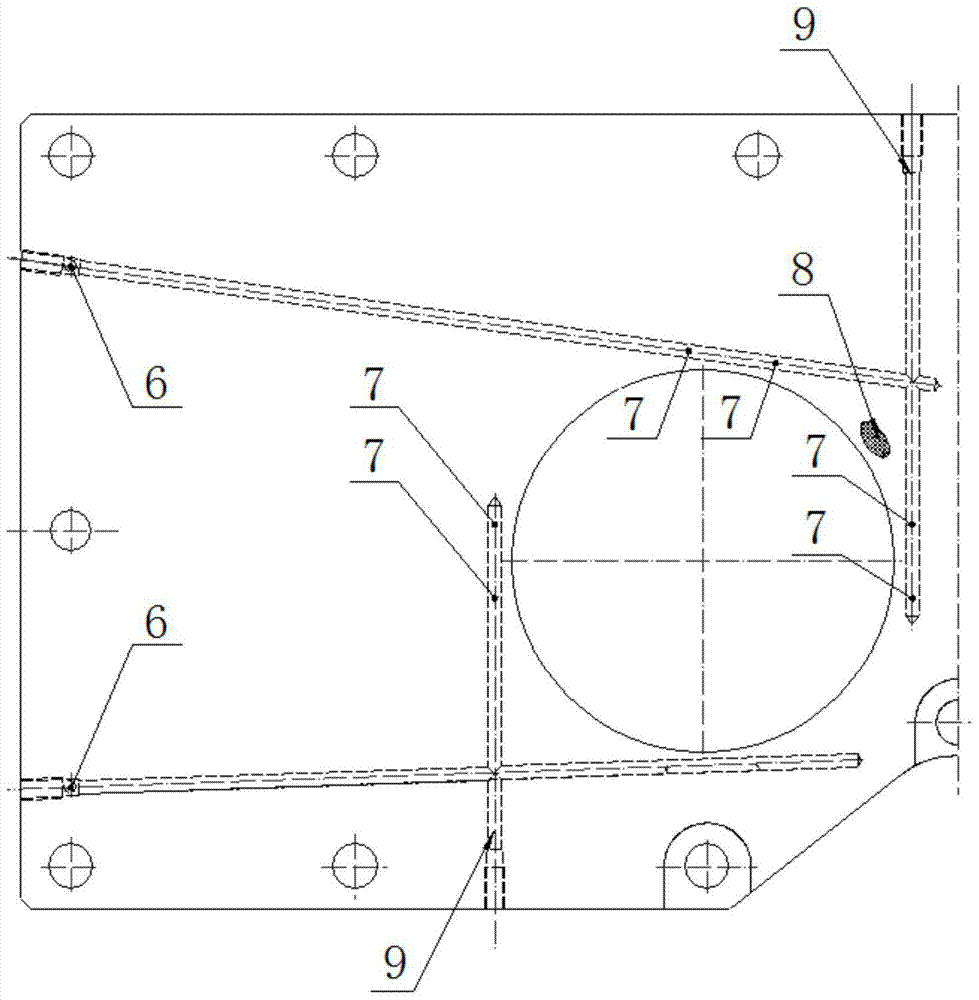
[0019] figure 1 It is a schematic diagram of the assembly of the roll box and roll shaft of the finishing mill. The double-lip seal 3 is installed on the seal seat 5, and the upper and lower lips of the double-lip seal 3 are axially compressed with the upper oil flinger 2 and the lower oil flinger 4 to form an interference to realize the sealing effect. figure 2 It is a structural schematic diagram of the roll box seal seat of the finishing mill in the prior art. The roll box seal seat 5 of the finishing mill in the prior art is a whole, and the shaft seal water has four seal seat shaft seal water inlet holes 6 input, and by adding four Shaft seal water process holes 9 form a total of eight channels inside to transport the shaft seal water to 16 seal seat shaft seal water outlet holes 7 . The inner hole of the double lip seal of the sealing seat 5 is worn, the waterway of the shaft seal is blocked, or a pit 8 is formed on the surface. Only by replacing the assembly of the se...


PUM


Abstract

The invention discloses a sealing base device for a high-line finishing mill roll box. The sealing base device comprises an inverted-V-shaped plate, a partition ring and inner hexagonal countersunk bolts. The partition ring is fixedly installed on the inverted-V-shaped plate through the inner hexagonal countersunk bolts. A plurality of inclined small holes with the rotating angle the same as that of a roller ring are formed in the upper surface of the partition ring. The small holes are uniformly distributed in the middles of lip sides and the bottom sides of double lip seals. The small holes are communicated with an outer diameter water path of the partition ring. The outer diameter water path of the partition ring is connected with a water inlet hole of the inverted-V-shaped plate. Shaft sealing water entering from the inverted-V-shaped plate is conveyed to an annular water path of the partition ring through the inverted-V-shaped plate, and enters a sealing cavity from a shaft seal water outlet of the partition ring to the upper surface of the partition ring. The sealing base device for the high-line finishing mill roll box is provided with a structure, as the partition ring is additionally arranged on a sealing base, when pits are formed after the double lip seals are assembled and disassembled many times and flushed, the situations that the double lip seals fall off and cooling water enters the sealing cavity can be eliminated by replacing the partition ring, the service life of the sealing base and the double lip seals is prolonged obviously.

Description

technical field [0001] The invention relates to the technical field of rolling equipment, in particular to a sealing seat device used for a roll box of a high-line finishing mill. Background technique [0002] The isolation between the inside and the outside of the roll box of the high-speed wire rolling line finishing mill is to adopt a double-lip seal and install it on the sealing seat. The two lips of the double-lip seal and the upper and lower oil throwing rings are axially compressed, and the lips shrink inward to form a pass. realized by surplus. Double-lip seal The outer lip isolates cooling water, iron filings, dust, etc., and the inner lip isolates lubricating oil to prevent lubricating oil from leaking. The height of the axial compression between the double-lip seal and the flinger is determined by the seal seat. The cooperation between the seal seat and the double-lip seal is very critical. Frequent replacement of the double-lip seal will wear the inner hole of t...

Claims


Application Information

Patent Timeline
Patent Type & Authority Patents(China)
IPC IPC(8): B21B31/02F16J15/3232
CPCB21B31/02F16J15/3232
Inventor 张本练宋强王金来刘朝彤孙山
Owner MAANSHAN IRON & STEEL CO LTD
Why Eureka
Try Eureka