Method for axial correction in a processing machine, as well as a processing machine

一种加工机、加工轴的技术,应用在印刷机、轮转印刷机、容器制造机械等方向

Inactive Publication Date: 2009-02-11
ROBERT BOSCH GMBH
View PDF0 Cites 1 Cited by
  • Summary
  • Abstract
  • Description
  • Claims
  • Application Information

AI Technical Summary

Problems solved by technology

[0008] The disadvantage of these measures is that, during the acceleration process, errors in registration and in the web tension are taken into account not on the basis of the current acceleration value but on the basis of a fixedly stored acceleration value, so that all errors that occur must be taken into account for the web tension adjustment adjust the adjustment difference of the register or register adjuster

Method used


Image

  • Method for axial correction in a processing machine, as well as a processing machine
  • Method for axial correction in a processing machine, as well as a processing machine
  • Method for axial correction in a processing machine, as well as a processing machine

Examples


Embodiment Construction

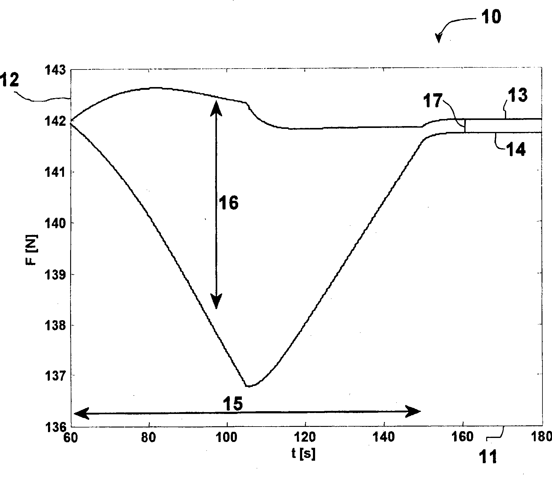
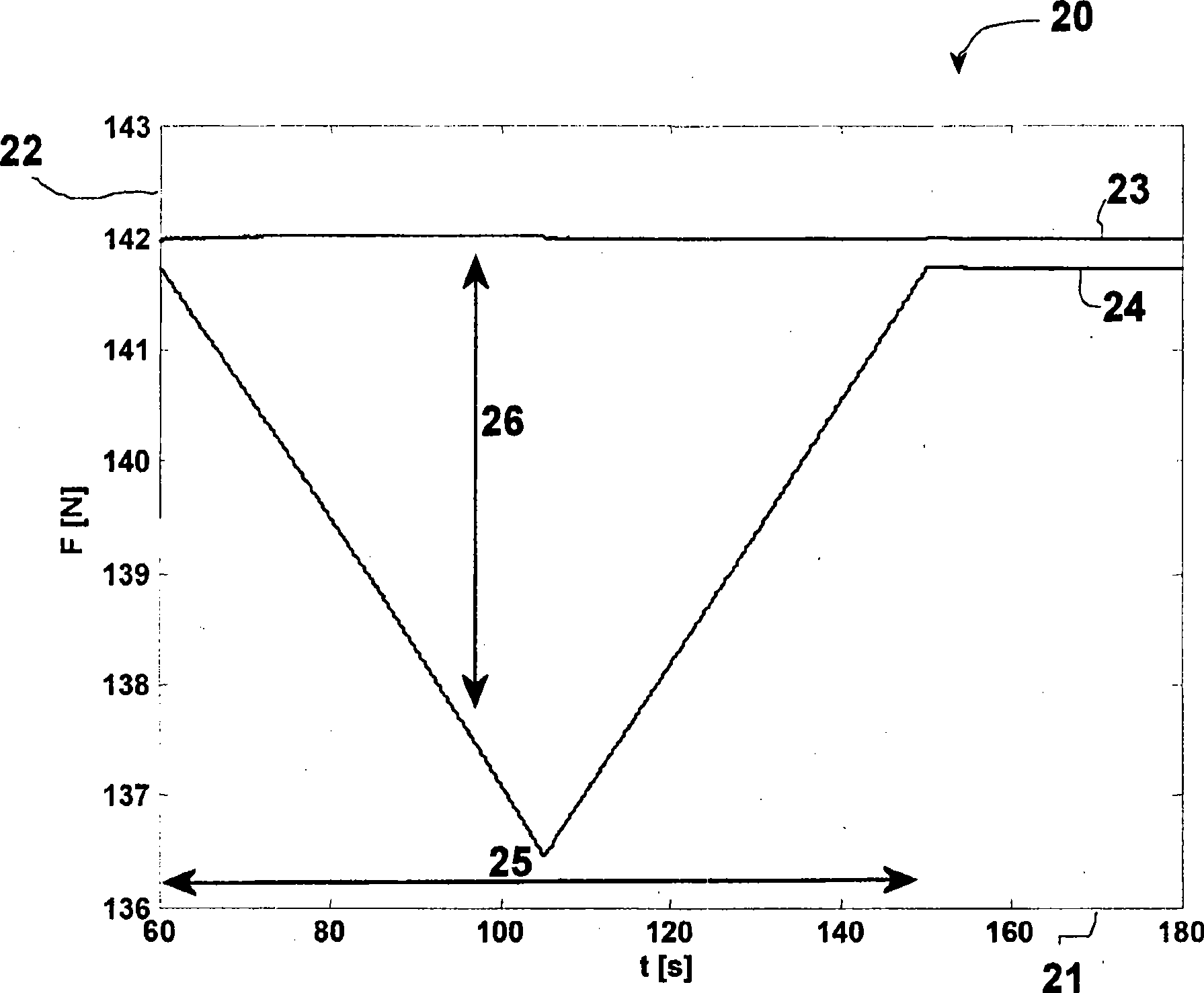
[0036] figure 1 The course of the web tension is plotted against time in diagram 10 in which two web tension courses 13 and 14 are shown. The web tension is plotted on the y-axis 12 in diagram 10 against time t on the x-axis 11 . figure 1 The profile of the web tension is shown in a dynamic situation in which the rollers involved in the work are accelerated.

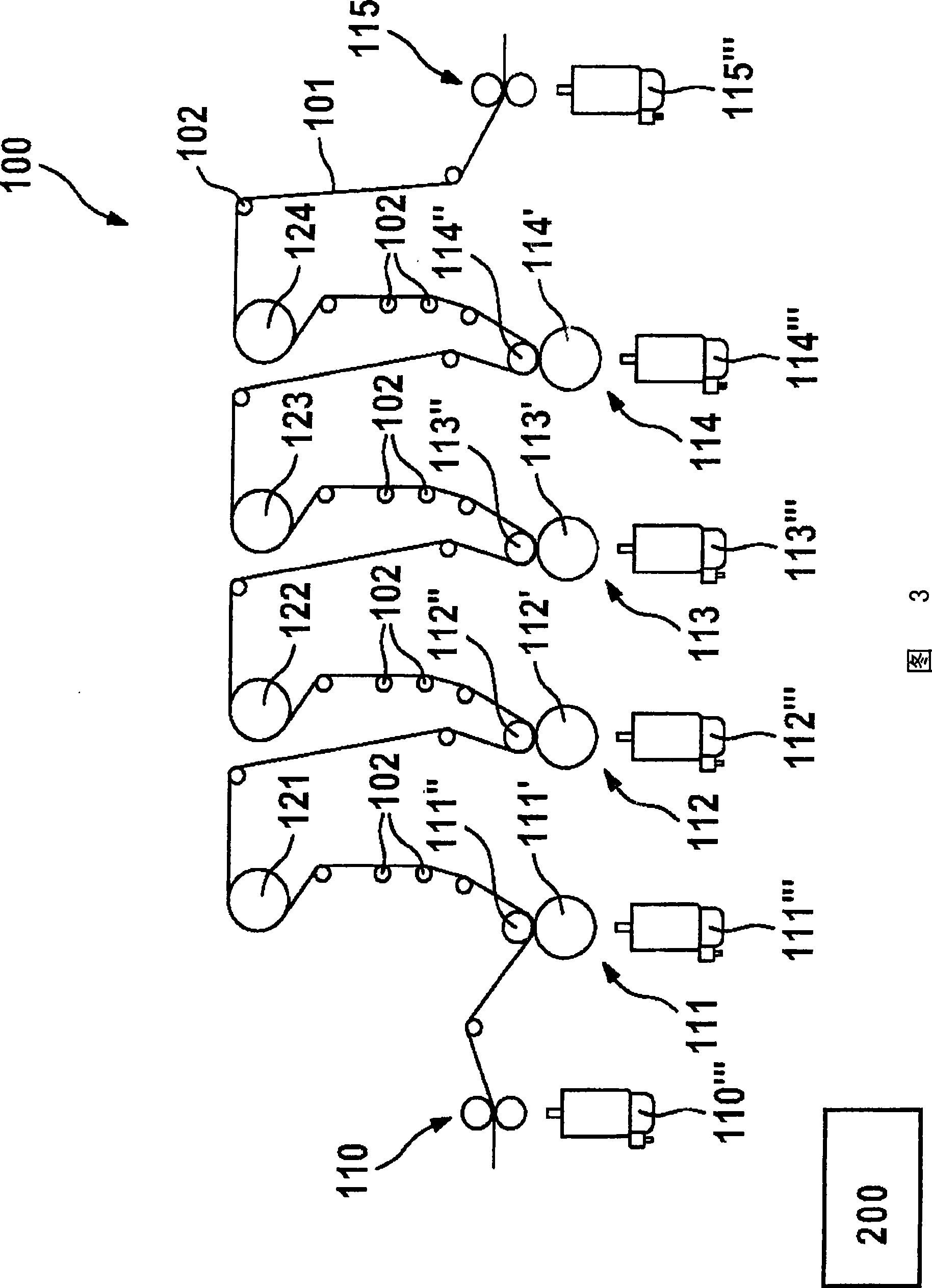
[0037] Diagram 10 shows two web tension curves 13 and 14 which are supposed to correspond to different web tension subsections. A web tensioning section is considered here, which is divided by a non-driven shaft, in the exemplary embodiment shown, by a cooling roller into two adjacent web tensioning subsections. At the ends of the web tensioning sections there are in each case a clamping point (driven shaft), in the illustrated exemplary embodiment a driven pressure roller. Referring to FIG. 3 , for example, between the printing unit 112 and the printing unit 113 , a web tensioning section as described can be seen, wh...


PUM


Abstract

A method for axial correction in a processing machine, which has at least two driven transport axles for transporting and processing a product web, at least one non-driven or driven processing axle, and at least one additional non-driven axle, wherein the product web is divisible into at least one web-tensioning segment; a web-tensioning segment is delimited by two clamping points embodied in the form of driven transport or processing axles; ; and during a rotation speed change of a clamping point delimiting a web-tensioning segment, a pilot control of this clamping point delimiting the web-tensioning segment and / or of a processing axle situated in this web-tensioning segment is carried out, taking into account a moment of inertia of a non-driven axle situated in this web-tensioning section, and a corresponding processing machine.

Description

technical field [0001] The invention relates to a method for axis alignment on a processing machine, as well as to a corresponding processing machine, a corresponding computer program and a corresponding computer program product. [0002] Although the following mainly refers to printing machines, the invention is not restricted thereto, but rather relates to all types of processing machines with driven and non-driven shafts or rollers. The invention can be used in particular on printing presses such as newspaper printing presses, odd-print printing presses, gravure printing presses, packaging printing presses or security printing presses and on processing machines such as bag making machines, envelope making machines or packaging machines. Background technique [0003] On processing machines, especially printing machines, the product web is moved along driven axes (web transport axes), such as pinch rollers or feed rollers, and non-driven axes such as deflection rollers, gui...

Claims


Application Information

Patent Timeline
Patent Type & Authority Applications(China)
IPC IPC(8): B65H23/188B65H20/02B41F13/02B41F33/06B31B1/10B65B41/16B31B50/10
CPCB65H2513/30B41F13/02B65H2515/10B65H23/1888B65H2220/03B65H2220/01
Inventor S·舒尔茨H·施纳贝尔
Owner ROBERT BOSCH GMBH
Why Eureka
Try Eureka