Vane compressor

A compressor and vane technology, which is applied in the field of vane compressors, can solve problems such as increased start-up delay and longer start-up oscillation generation time, and achieve the effect of improving compression performance

Inactive Publication Date: 2009-02-11
CALSONIC KANSEI CORP
View PDF1 Cites 8 Cited by
  • Summary
  • Abstract
  • Description
  • Claims
  • Application Information

AI Technical Summary

Problems solved by technology

[0006] As mentioned above, the vane compressor using the pressure of the centrifugal pump and its own discharge pressure starts to increase the vane back pressure after starting, so the start-up delay increases accordingly, and the time for the start-up oscillation to occur becomes longer.

Method used


Image

  • Vane compressor
  • Vane compressor
  • Vane compressor

Examples


no. 1 Embodiment approach

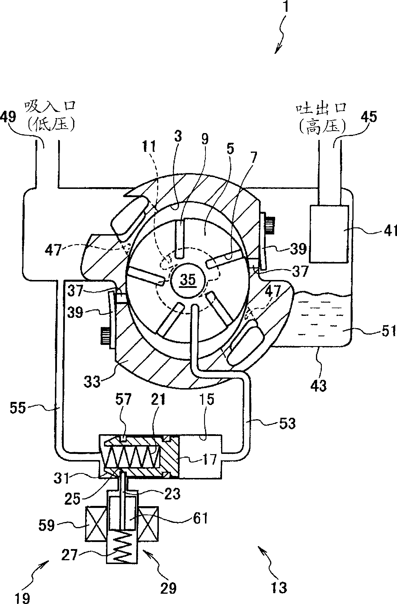
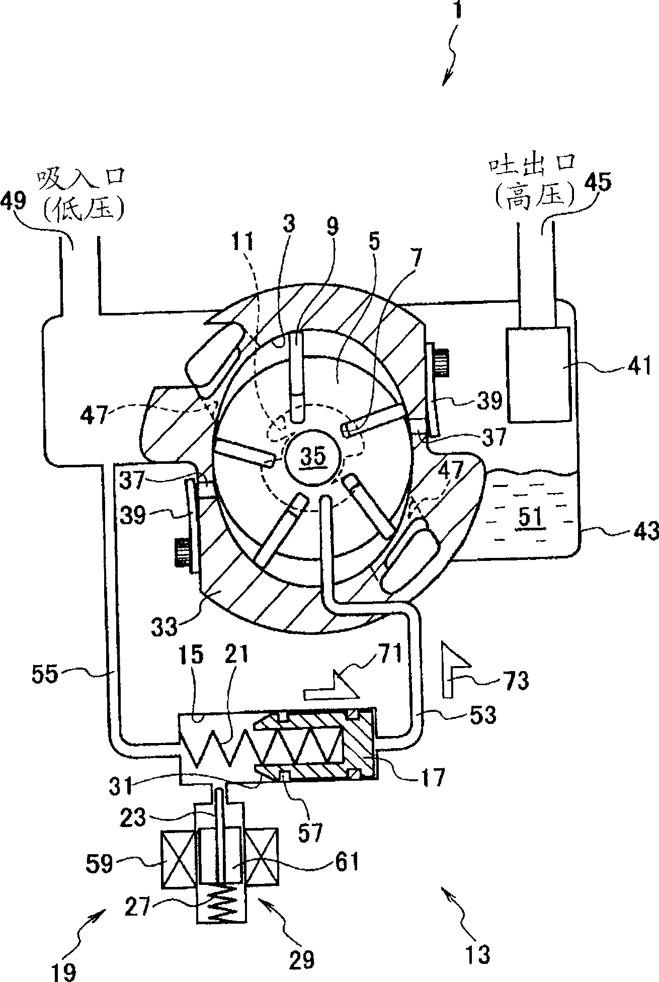
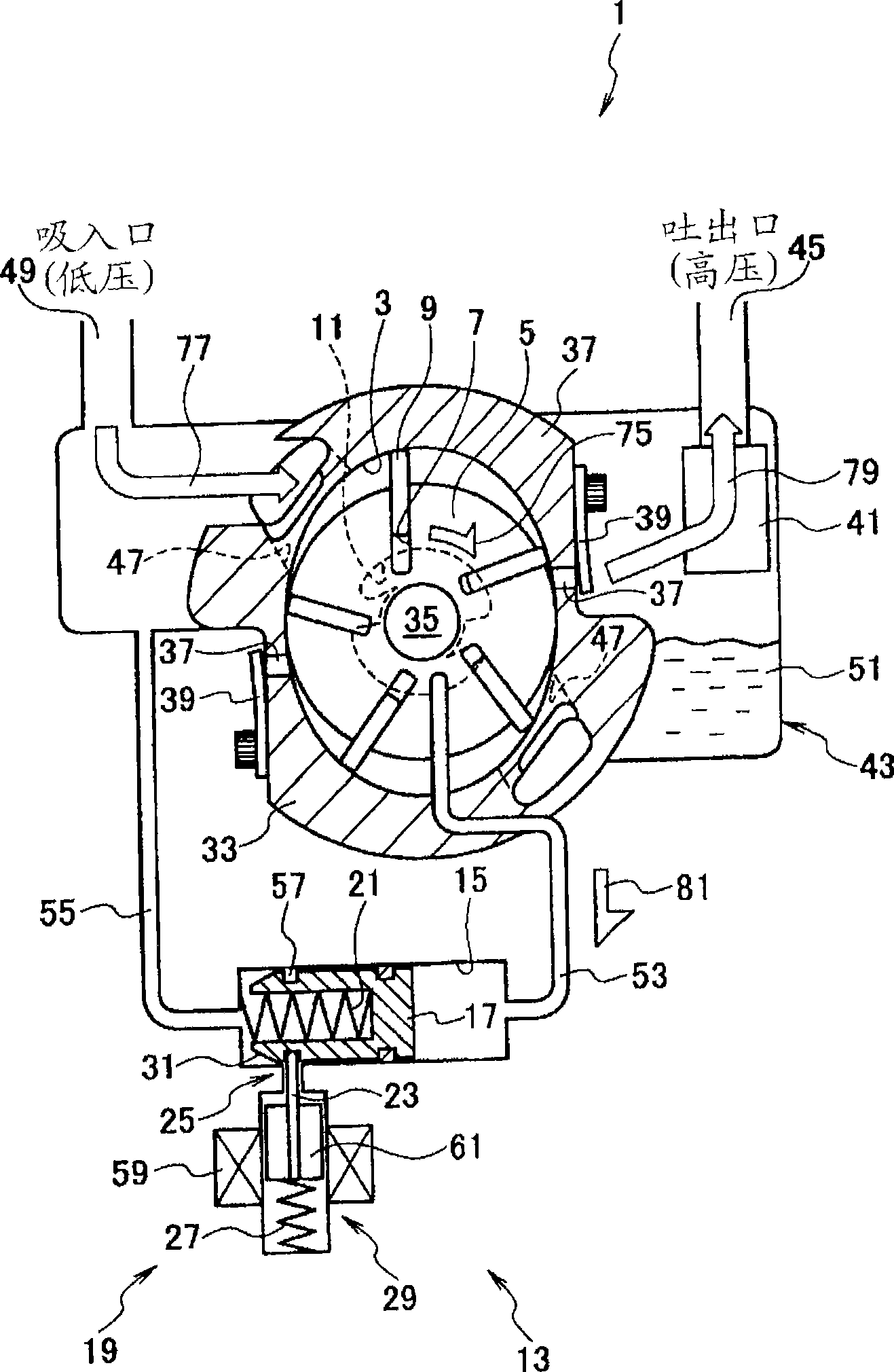
[0037] Figure 1 ~ Figure 3 Showing the first embodiment of the present invention, figure 1 is a sectional view of main parts of the vane compressor 1 in a standby state, figure 2 is a sectional view of main parts of the vane compressor 1 when the startup mode is selected, image 3 It is a cross-sectional view of main parts of the vane compressor 1 in a state where the back pressure supply member 13 and the position maintaining member 19 are reset.

[0038]The vane compressor 1 includes a cylinder chamber 3, a rotor 5, a vane groove 7, a vane 9, a vane back pressure chamber 11, and a back pressure supply member 13; the rotor 5 is freely rotatably arranged in the cylinder chamber 3; Arranged on the rotor 5 at equal intervals in the circumferential direction; the above-mentioned blades 9 are arranged in the blade grooves 7 and can freely protrude into the cylinder chamber 3 and sink into the blade grooves 7; the above-mentioned blade back pressure chambers 11 communicate with...

no. 2 Embodiment approach

[0064] Figure 4 ~ Figure 6 Showing the second embodiment of the present invention, Figure 4 is a sectional view of main parts of vane compressor 101 in a standby state, Figure 5 is a sectional view of main parts of the vane compressor 101 when the startup mode is selected, Figure 6 It is a cross-sectional view of main parts of the vane compressor 101 in a state where the back pressure supply member 103 and the opening and closing member 109 are reset.

[0065] The vane compressor 101 includes a cylinder chamber 3, a rotor 5, a vane groove 7, a vane 9, a vane back pressure chamber 11 and a back pressure supply member 103; the rotor 5 is freely rotatably arranged in the cylinder chamber 3; the vane groove 7 is arranged along the Arranged on the rotor 5 at equal intervals in the circumferential direction; the above-mentioned blades 9 are arranged in the blade grooves 7 and can freely protrude into the cylinder chamber 3 and sink into the blade grooves 7; the above-mentioned...


PUM


Abstract

A vane compressor (1) able to prevent the start delay and start oscillation including: a cylinder chamber (3); a rotor (5) rotatably arranged in the cylinder chamber (3); vane grooves (7) provided in the rotor (5) at equal intervals in the circumferential direction thereof; vanes (9) arranged in the vane grooves (7) in a way that the vanes (9) are capable of protruding to, and retracting from, the cylinder chamber (3); and the vane back-pressure chamber (11) communicating with the bottom portions of the vane grooves (7), and configured to apply the back pressure to the vanes (9); and a back-pressure supplying unit (13) configured to transmit the pressure to the vane back-pressure chamber (11), and to push up the vanes to the sliding surface of the cylinder chamber (3) once the activation mode for rotating the rotor (5) is selected.

Description

technical field [0001] The present invention relates to a vane compressor in which a compression chamber is formed in a cylinder chamber by vanes protruding from a rotor. Background technique [0002] As a conventional example of a vane compressor, there is a vane compressor disclosed in Patent Document 1. As shown in FIG. When the rotor rotates, the vane of the vane groove is pushed out by the centrifugal force and the back pressure generated by the discharge pressure to come into close contact with the sliding surface of the cylinder chamber, and the vane compressor starts to compress the gas. Furthermore, in order to promote vane movement and close contact between the vane and the sliding surface of the cylinder chamber at startup, a centrifugal pump driven by the rotation of the rotor is provided, and back pressure is sent from the centrifugal pump to the vane back pressure chamber. [0003] Patent Document 1: Japanese Patent Laid-Open No. 2004-190509 [0004] However,...

Claims


Application Information

Patent Timeline
Patent Type & Authority Applications(China)
IPC IPC(8): F04C18/344F04C29/00F04C28/06
CPCF04C2/3446F01C21/0863
Inventor 上岛义武
Owner CALSONIC KANSEI CORP
Why Eureka
Try Eureka