Main bearing for wind power generation

A main bearing and outer ring technology, applied in bearings, bearing components, shafts and bearings, etc., can solve the problems of large impact of the main shaft on the gearbox and generator, inconvenient maintenance and disassembly, and damage to the gearbox, and achieve easy maintenance and disassembly , Realize the transmission of force and prolong the service life

Inactive Publication Date: 2009-02-11
包头市汇全稀土实业(集团)有限公司
View PDF0 Cites 9 Cited by
  • Summary
  • Abstract
  • Description
  • Claims
  • Application Information

AI Technical Summary

Problems solved by technology

This structure is rigidly connected, and the main shaft will have a great impact on the gearbox and generator, which will easily cause premature damage to the gearbox, and it is extremely inconvenient to repair and disassemble.

Method used


Image

  • Main bearing for wind power generation

Examples


Embodiment Construction

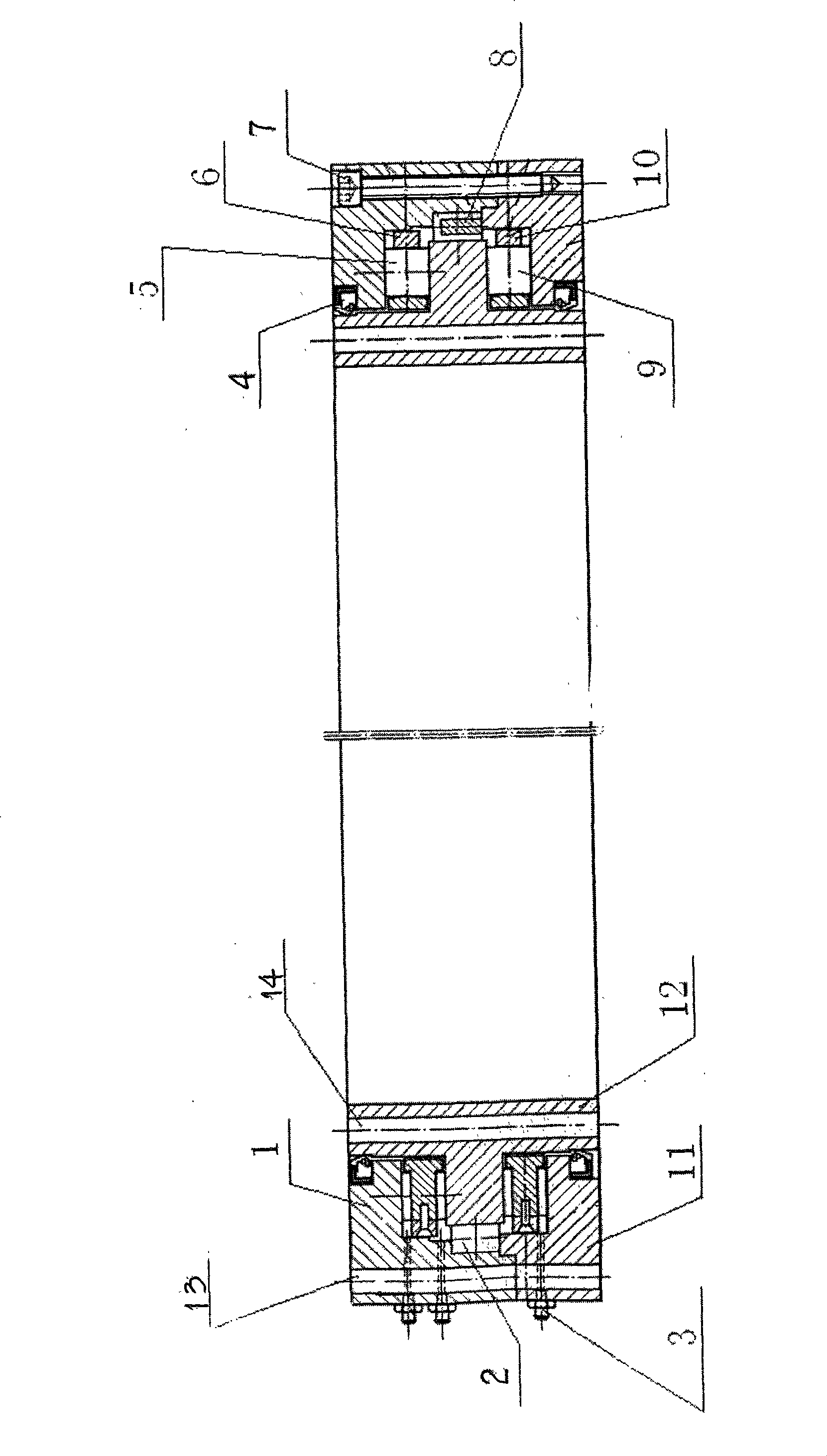
[0014] The inner side of the lower outer ring 11 of the main bearing of the present invention is provided with upper and lower rows of thrust cylindrical rollers 5 and 9, and the outer side of the main bearing inner ring 12 is provided with a single row of centripetal cylindrical rollers 2, cylindrical rollers 2 Place on the cage 8, the cage 10 is placed on the inner step of the lower outer ring 11 of the main bearing, the thrust cylindrical roller 9 is placed in the roller position of the cage 10, and the inner ring 12 of the main bearing is placed on the main bearing In the inner ring of the outer ring 11, a cage 8 is placed outside the inner ring 12 of the main bearing, and the single-row radial cylindrical roller 2 is placed on the cage 8, and the inner ring of the outer ring 11 of the main bearing located under the cage 8 The cage 6 is placed on the steps, the thrust cylindrical roller 5 is placed in the roller position of the cage 6, the upper outer ring 1 of the main bea...


PUM


Abstract

The invention relates to a wind power generation main bearing which belongs to the aerogenerator field, the wind power generation main bearing is characterized by comprising a main bearing upper limb, a main bearing lower limb, an anti-thrust cylindrical roller and a holder; the inner sides of the main bearing inner limb and the main bearing lower limb are provided with two rows of anti-thrust cylindrical rollers; the outer side of the main bearing inner limb is provided with a single row of centripetal cylindrical rollers and the cylindrical rollers are placed on the holder. The bearing of the invention saves a main shaft so that the impact of an original stiff shaft on a gear box and a generator can be reduced greatly and the service life of the gear box and the generator can be prolonged; the transmission of power can be realized well and the main bearing of the invention is easy to be repaired and detached. The main bearing can stand axial force with big load and big radial load, which can be well suitable for the working condition of aerogenerators with no main shaft, thus meeting the stress requirements of the aerogenerator.

Description

1. Technical field [0001] The invention relates to a main bearing for wind power generation, which belongs to the field of wind power generators. 2. Background technology [0002] At present, the structure of the known wind power generator with gearbox is that the main bearing is placed in the main bearing seat, the main bearing seat is fixedly connected with the nacelle floor, one end of the main shaft is connected with the wheel hub, and the other end is connected with the gearbox through the main bearing seat, and the gearbox Connected to generator. This structure is rigidly connected, and the main shaft has a great impact on the gearbox and generator, which may easily cause premature damage to the gearbox, and it is extremely inconvenient to repair and disassemble. 3. Contents of the invention [0003] The purpose of the present invention is to provide a main bearing for wind power generation that can reduce the impact on the gearbox and the generator, prevent the gea...

Claims


Application Information

Patent Timeline
Patent Type & Authority Applications(China)
IPC IPC(8): F16C19/50F16C33/66F16C33/78F16C33/58
CPCF16C2300/14F16C19/381F16C2360/31
Inventor 张富全
Owner 包头市汇全稀土实业(集团)有限公司
Why Eureka
Try Eureka