
Mosquito driving and lighting lamp

A lighting and mosquito repelling technology, which is applied in lighting devices, lighting devices, lighting and heating equipment, etc., can solve the problems of lack of sterilization, deodorization, air purification, mosquito killing effect affected by light, and unsuitable for home use. , to achieve a good mosquito repellent effect, a wide range of dispersal, and the effect of preventing high-voltage electric shock

Inactive Publication Date: 2009-02-11
NINGBO TALLER ELECTRICAL APPLIANCE CO LTD
View PDF3 Cites 9 Cited by
  • Summary
  • Abstract
  • Description
  • Claims
  • Application Information

AI Technical Summary

Problems solved by technology

Compared with the traditional method of installing mosquito repellent sheets on incandescent lamps, this patent uses a mosquito repellent lamp tube and uses the principle of spectrum to kill mosquitoes. However, the light emitted by the mosquito repellent lamp tube can kill mosquitoes within a certain effective distance. Effect, the anti-mosquito effect is affected by light, and once the phosphor layer on the inner wall of the lamp tube is damaged or falls off, the entire lamp tube must be replaced to achieve the mosquito repellent effect, which increases the cost of use
Moreover, this mosquito repellent lamp can only play a role in killing mosquitoes, and does not have the effects of sterilization, deodorization, and air purification.
[0004] In addition, there are currently some mosquito killer lamps that use suction and high-voltage power grids to eliminate mosquitoes and flies. However, this kind of mosquito killer lamps has the risk of electric shock during use, and is not safe to use, so it is not suitable for home use.

Method used


Image

  • Mosquito driving and lighting lamp
  • Mosquito driving and lighting lamp
  • Mosquito driving and lighting lamp

Examples


Embodiment Construction

[0040] The present invention will be further described in detail below with reference to the embodiments of the drawings.

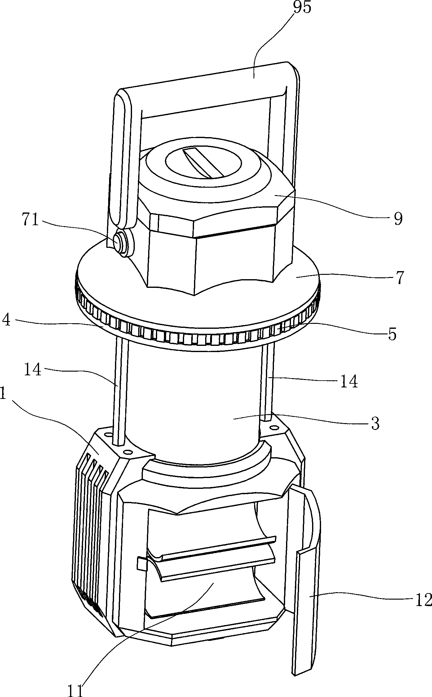
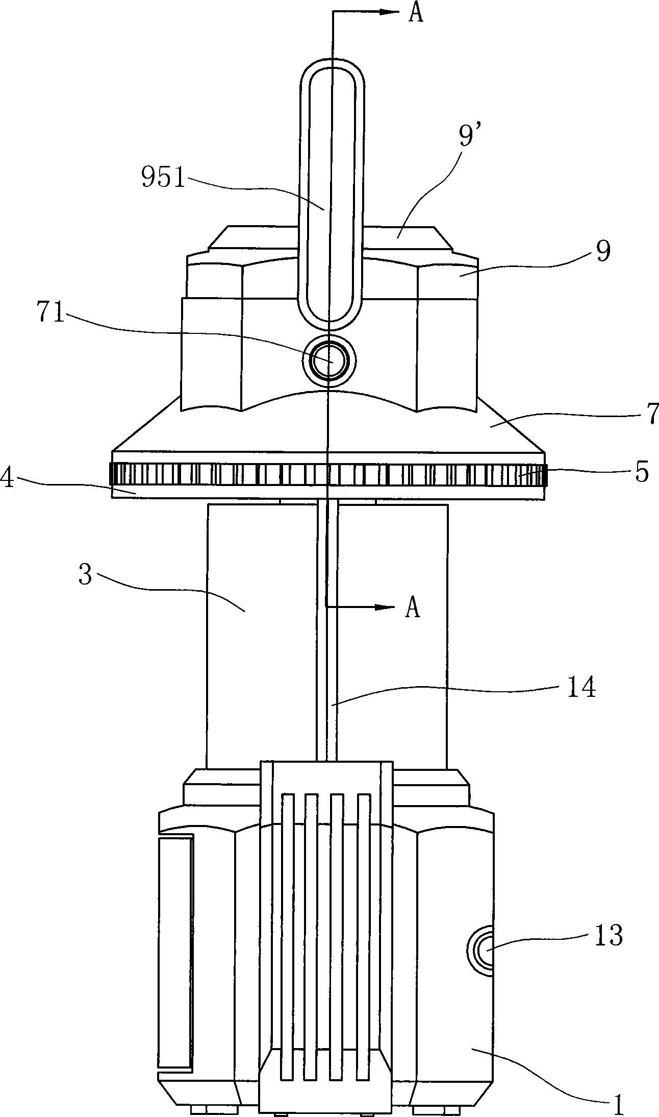
[0041] Examples, see Figure 1~Figure 9 :

[0042] The mosquito repellent lighting lamp in this embodiment includes a lamp holder 1, an LED lighting tube 2 and a lamp shade 3. The LED lighting lamp tube 2 is installed in a transparent lamp shade 3, and the lamp shade 3 is fixed on the lamp socket 1. The lamp holder 1 has a cavity 11 in which batteries can be installed. The cavity 11 is also provided with a swing door 12 that can be opened and closed. On the outer surface of the lamp holder 1, there is also a battery that is electrically connected to the battery in the cavity 11. The connected power switch 13 is used to control the on and off of the lamp tube 2. In this embodiment, dry batteries or rechargeable batteries can be used to power the lamp tube, which is safer to use and can effectively prevent high-voltage electric shocks.

[0043] A circular chassis ...


PUM


Abstract

A mosquito repelling lighting lamp comprises a light base, where a lamp screen provided with a lighting lamp tube is arranged; a power supply switch which controls the conduction and deenergization of the lamp tube; a mosquito repelling device which is arranged above the light screen; the mosquito repelling lighting lamp is characterized in that: the mosquito repelling device is provided with a chamber which can hold mosquito repelling tablets and the chamber is provided with an air inlet and an air outlet which are communicated with each other; in the position corresponding to the air inlet, a fan is arranged, and is electrically connected with the lamp tube through a conversion circuit board. Moreover, the conversion circuit board is connected with a fan switch which controls the fan to rotate and stop. Compared with the prior art, the mosquito repelling lighting lamp is provided with the air inlet and the air outlet in the mosquito repelling device and the airflow produced by the rotation of the fan dispels the drug efficacy of the mosquito repelling tablets out of the air outlet, thus achieving a better mosquito repelling effect. Inside the mosquito repelling device, besides the mosquito repelling tablet, an aromatic or a deodorizer can also be arranged to achieve the aim of purifying air or incensing.

Description

Technical field [0001] The invention relates to a mosquito-repellent lighting lamp, which can realize the mosquito-repellent effect while illuminating, and can simultaneously have the functions of sterilization, deodorization and air purification. Background technique [0002] Considering the mosquito bites in summer, people in the early days thought of adding additional mosquito repellent devices along with the lighting, such as the Chinese utility model patent "Additional device for mosquito repellent incense for lighting fixtures" with the patent number CN87203596, and the patent number CN85202716 The Chinese utility model patent "Lighting and Mosquito Repellent Bulbs" both have positions or additional devices for placing mosquito repellents on the bulbs. When the bulbs are lit, the residual heat of the bulbs can be used to heat the mosquito repellents to repel mosquitoes. However, the mosquito repellent or incense tablets in the above-mentioned patents use the waste heat of t...

Claims


Application Information

Patent Timeline
Patent Type & Authority Applications(China)
IPC IPC(8): F21V33/00F21V23/00A01M13/00F04D25/08
CPCA01M29/12
Inventor 沈建立
Owner NINGBO TALLER ELECTRICAL APPLIANCE CO LTD
Learn More