Mobile joint unit for switch and switch device using the same

A technology for moving contacts and switches, applied in the field of movable contact units for switches, can solve problems such as the inability of the movable contacts to operate normally, the insufficient light intensity of the operation keys, and the malfunction of the switch elements, etc., to achieve good assembly operability and improve assembly operability. , the effect of reducing power consumption

Inactive Publication Date: 2009-02-11
ALPS ALPINE CO LTD
View PDF1 Cites 6 Cited by
  • Summary
  • Abstract
  • Description
  • Claims
  • Application Information

AI Technical Summary

Problems solved by technology

However, if the flexible light guide plate is laminated on the flexible thin plate, the light introduced into the light guide plate from the side end surface will easily leak into the flexible thin plate and be scattered due to the close contact between the two. The undesired parts near the operation keys are illuminated. Due to the light loss caused by this, the amount of light on the operation keys far away from the light source is insufficient, which easily causes other problems such as uneven illumination.
[0006] In addition, as in the prior art disclosed in Patent Document 1, there is also a switch device in which the movable contact of each switch elemen...

Method used


Image

  • Mobile joint unit for switch and switch device using the same
  • Mobile joint unit for switch and switch device using the same
  • Mobile joint unit for switch and switch device using the same

Examples


Embodiment Construction

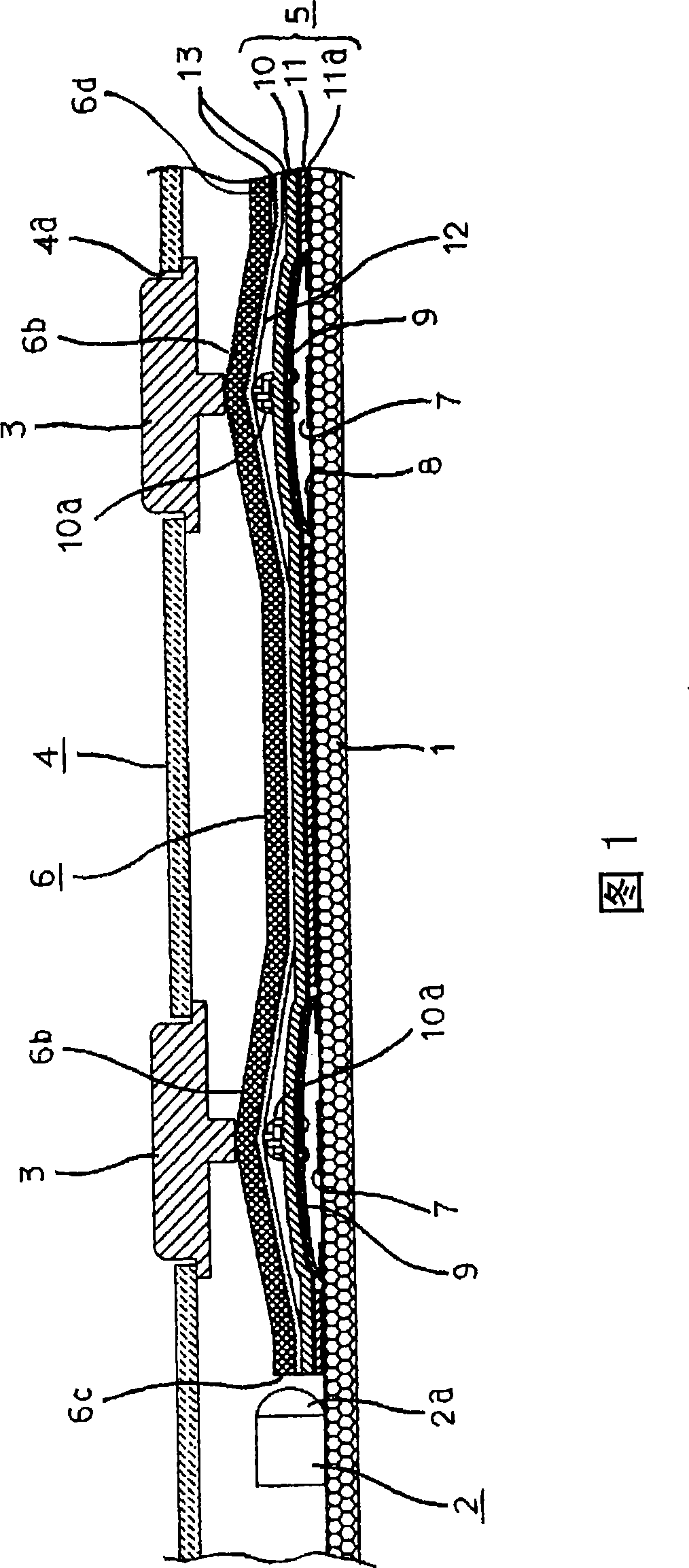
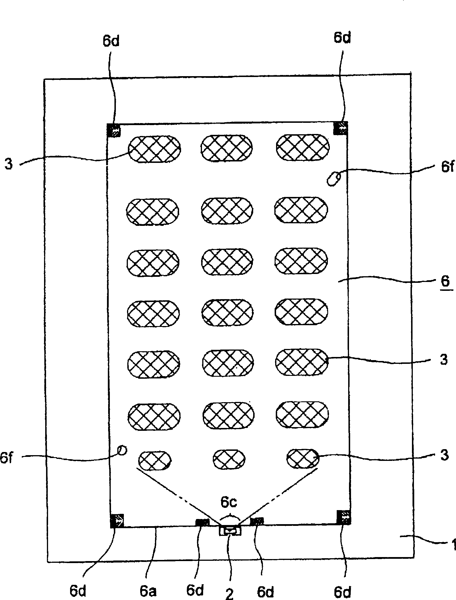
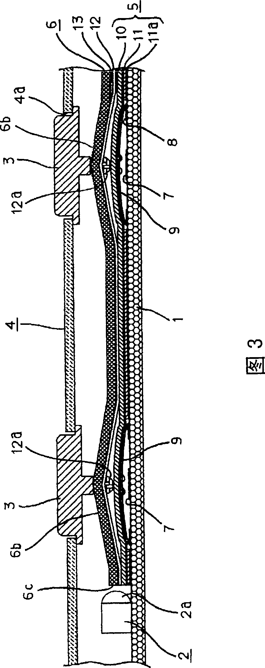
[0021] Next, with reference to the accompanying drawings, the embodiment of the present invention will be described. Fig. 1 is a sectional view of main parts of a switchgear according to Embodiment 1 of the present invention, figure 2 It is a top view showing the switchgear shown in FIG. 1 omitting a cover body.

[0022] The switch device shown in these figures mainly includes: a substrate 1 on which LED 2 is mounted, a plurality of operation keys 3 arranged in the opening 4a of the cover body 4, an attached contact thin plate member 5 placed on the substrate 1, and an attached contact on the attached contact. The flexible light guide plate 6 that prevents the thin plate 12 from being laminated is interposed on the thin plate member 5 . On the upper surface of the substrate 1, fixed contacts 7 and common contacts 8 are disposed below the respective operation keys 3, and the two contacts 7, 8 are exposed at regular intervals. In addition, on the substrate 1 , unillustrated wir...


PUM


Abstract

The invention provides a movable connection point unit for switch and a switch using the same. Wherein a LED (2) as light source is mounted on a substrate (1), a luminous section (2a) of the LED is opposite to a portion (light-in section 6c) of side end face (6a) of a flexible light guide board (6), and the light guided from the flexible light guide board (6) of the LED (2) is projected onto the bottom of an operation key (3) by an irradiation section (6b) of the light guide board (6). The flexible light guide board (6) is laminated on a flexible sheet (10) with separation of a joint sealing prevention sheet (12). A plurality of position under the flexible sheet (10) holds the movable connection point to make each movable connection point (9) and the fixing connection point (7) on the substrate (1) opposite in contactable separation mode. A plurality of protuberances (10a) capable of pressing central part of each movable connection point (9) respectively are arranged on smooth upper surface of the flexible sheet (10), such that the operation key (3) presses corresponding movable connection point (90) through the under protuberances (10a).

Description

technical field [0001] The present invention relates to a movable contact unit for a switch that is assembled in a switch device provided with a plurality of switch elements that are respectively pressed and driven by a plurality of operation keys, and illuminates the group of operation keys, and a device using the light-emitting member for a switch. switchgear. Background technique [0002] In recent years, as an input unit of a mobile phone, etc., a switch device with a lighting function has been proposed (for example, refer to Patent Document 1). The light source is arranged in the upper part, and the light guide plate is placed on the substrate in such a way as to cover the switch element group. By connecting the light source to the substrate, it is possible to fix the movable contacts of each switch element to each operation key through the light guide plate. While the contacts are pushed and driven, the light from the light source introduced into the light guide plate...

Claims


Application Information

Patent Timeline
IPC IPC(8): H01H13/70H01H13/83H01H13/704
CPCH01H9/181H01H13/02H01H13/702H01H13/83H01H2219/044H01H2219/056H01H2219/062H01H2219/0621H04M1/22H04M1/23
Inventor 岩间尚也斋藤充
Owner ALPS ALPINE CO LTD
Why Eureka
Try Eureka