Method for transmitting uncontinuous sending and unicontinuous receiving parameter of packet connection

A group connection and parameter technology, applied in the field of parameter transmission, to achieve the effect of ensuring data continuity

Inactive Publication Date: 2013-03-27
ZTE CORP
View PDF0 Cites 0 Cited by
  • Summary
  • Abstract
  • Description
  • Claims
  • Application Information

AI Technical Summary

Problems solved by technology

[0007] (2) Due to the concurrency of circuit domain and packet domain services, the user equipment is controlled by the traditional radio network controller RNC, but with the release of circuit domain services, because of load balancing, the traditional RNC needs to initiate The process of relocation;
[0008] (3) When the enhanced Node B is used as the serving Node B of the user equipment, the serving Node B generally has the best signal strength, and it has the function of serving the radio network controller RNC and combining the uplink packet data, but Due to the movement of the user equipment, the serving Node B needs to be updated frequently, and the function of the serving RNC must also be transferred frequently, thus requiring frequent relocation processes

Method used


Image

  • Method for transmitting uncontinuous sending and unicontinuous receiving parameter of packet connection
  • Method for transmitting uncontinuous sending and unicontinuous receiving parameter of packet connection

Examples


Embodiment 1

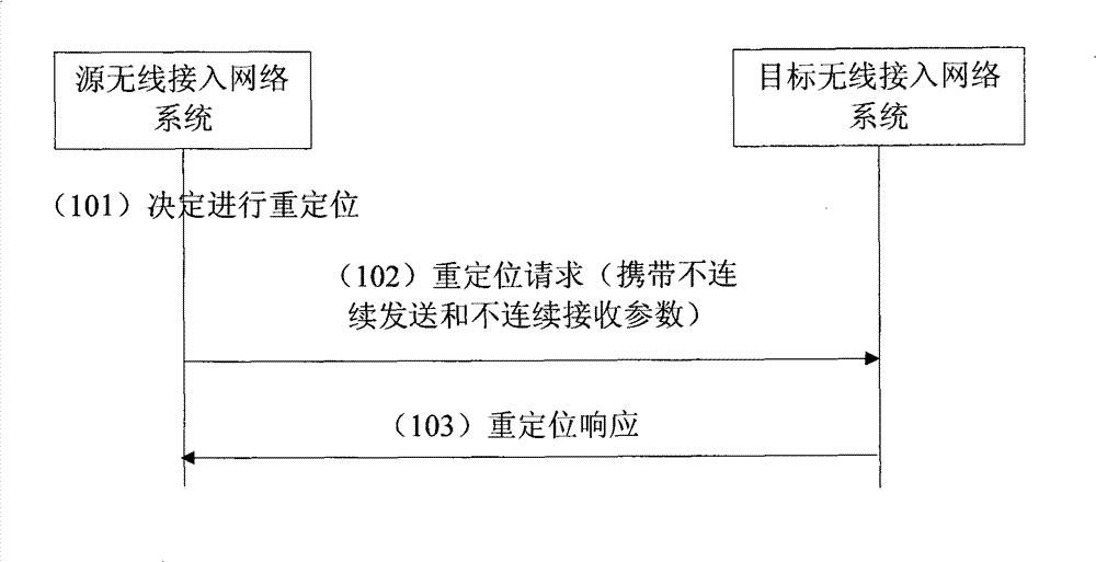
[0054] Embodiment 1 is a flowchart of a method for carrying discontinuous transmission and discontinuous reception parameters in which the source wireless access network system and the target wireless access network system directly exchange messages, as shown in figure 1 Shown:

[0055] Step 101: The source wireless access network system decides that a relocation process needs to be initiated;

[0056] Step 102: The source radio access network system initiates a relocation request message to the target radio access network system, which carries a "transparent container from the source radio network controller to the target radio network controller", and the "source radio network controller to the The "transparent container of the target radio network controller" also includes the "radio resource control container" information, and the "radio resource control container" includes parameter information related to discontinuous transmission and discontinuous reception;

[0057] S...

Embodiment 2

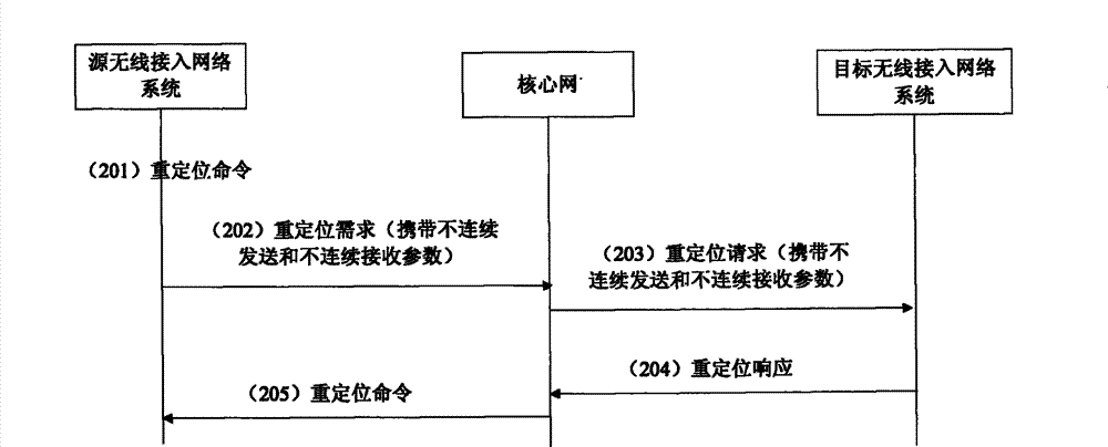
[0058] Embodiment 2 is a flowchart of a method for carrying discontinuous transmission and discontinuous reception parameters in which the source wireless access network system directly performs message interaction with the target wireless access network system through the core network, as shown in figure 2 Shown:

[0059] Step 201: The source radio access network system decides that a relocation process needs to be initiated;

[0060] Step 202: The source radio access network system sends a relocation request message to the core network, which carries a "transparent container from the source radio network controller to the target radio network controller", and the "source radio network controller to the target radio network controller "transparent container" contains "radio resource control container" information, and "radio resource control container" contains parameter information related to discontinuous transmission and discontinuous reception;

[0061] Step 203: The co...


PUM


Abstract

The invention relates to a wireless communication system, and discloses a method for transferring discontinuously sent and received parameters of a continuous block chaining. An active radio access network system informs a discontinuously sent and received related parameter message of a target wireless access network continuous block chaining directly through a signaling message or through the transparent forwarding of a core network. Through the addition of the discontinuously sent and received parameter of the continuous block chaining through 'a wireless control container', the parameter is directly sent by the active wireless access network system through 'relocation request' signaling carrying to the target wireless access network system, or transparently forwarded to the target access network system through the 'relocation request' of the core network signaling carrying, so as to allow the target wireless access network system to use.

Description

technical field [0001] The invention relates to a parameter transfer method in a wireless communication system, in particular to a method for discontinuously sending and discontinuously receiving parameters of a continuous packet connection. Background technique [0002] In order to reduce the transmission delay of packet domain data, the 3GPP protocol standard has evolved the protocol architecture of the third generation mobile communication, that is, the radio network controller (RNC) is moved down to the node B (NODEB), and the node B has a service radio Functions of the network controller, the control radio network controller, and the drift radio network controller, this kind of Node B may be referred to as an enhanced Node B for short. [0003] The downshift of the radio network controller has changed the interface definition between different nodes. The Iur interface is used between the enhanced node B and the enhanced node B, and the enhanced node B and the traditiona...

Claims


Application Information

Patent Timeline
Patent Type & Authority Patents(China)
IPC IPC(8): H04L1/00H04W48/08H04W48/16
Inventor 柯雅珠程翔张健
Owner ZTE CORP
Why Eureka
Try Eureka