Axial backlash-adjusted transmission drive unit

A drive unit, axial clearance technology, applied in the direction of components with teeth, transmission boxes, transmission parts, etc., to achieve the effect of eliminating the measurement process

Inactive Publication Date: 2009-02-11
ROBERT BOSCH GMBH
View PDF1 Cites 3 Cited by
  • Summary
  • Abstract
  • Description
  • Claims
  • Application Information

AI Technical Summary

Problems solved by technology

But here it is necessary to keep a very large number of different compensators

Method used


Image

  • Axial backlash-adjusted transmission drive unit
  • Axial backlash-adjusted transmission drive unit
  • Axial backlash-adjusted transmission drive unit

Examples


Embodiment Construction

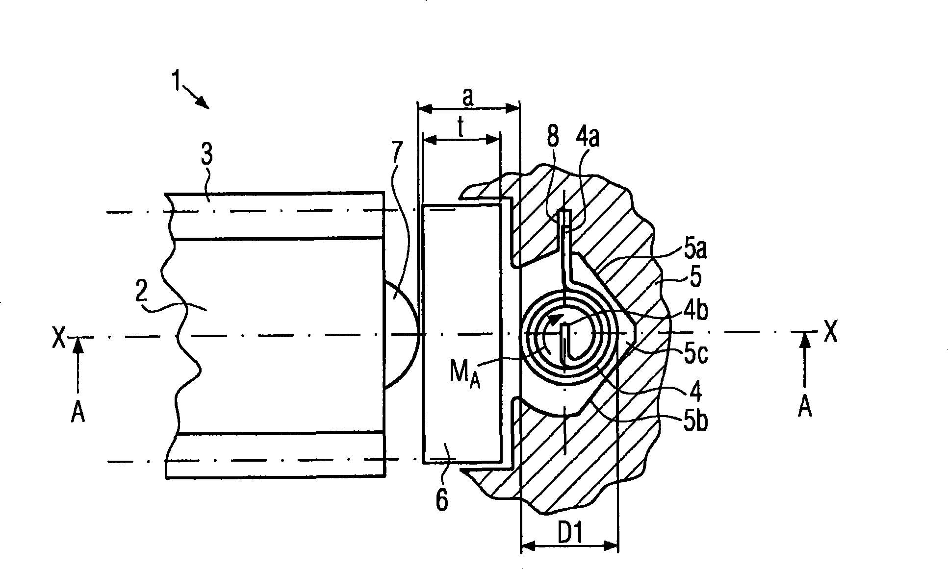
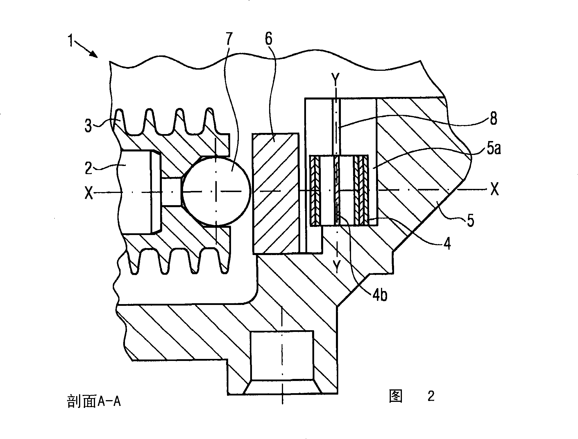
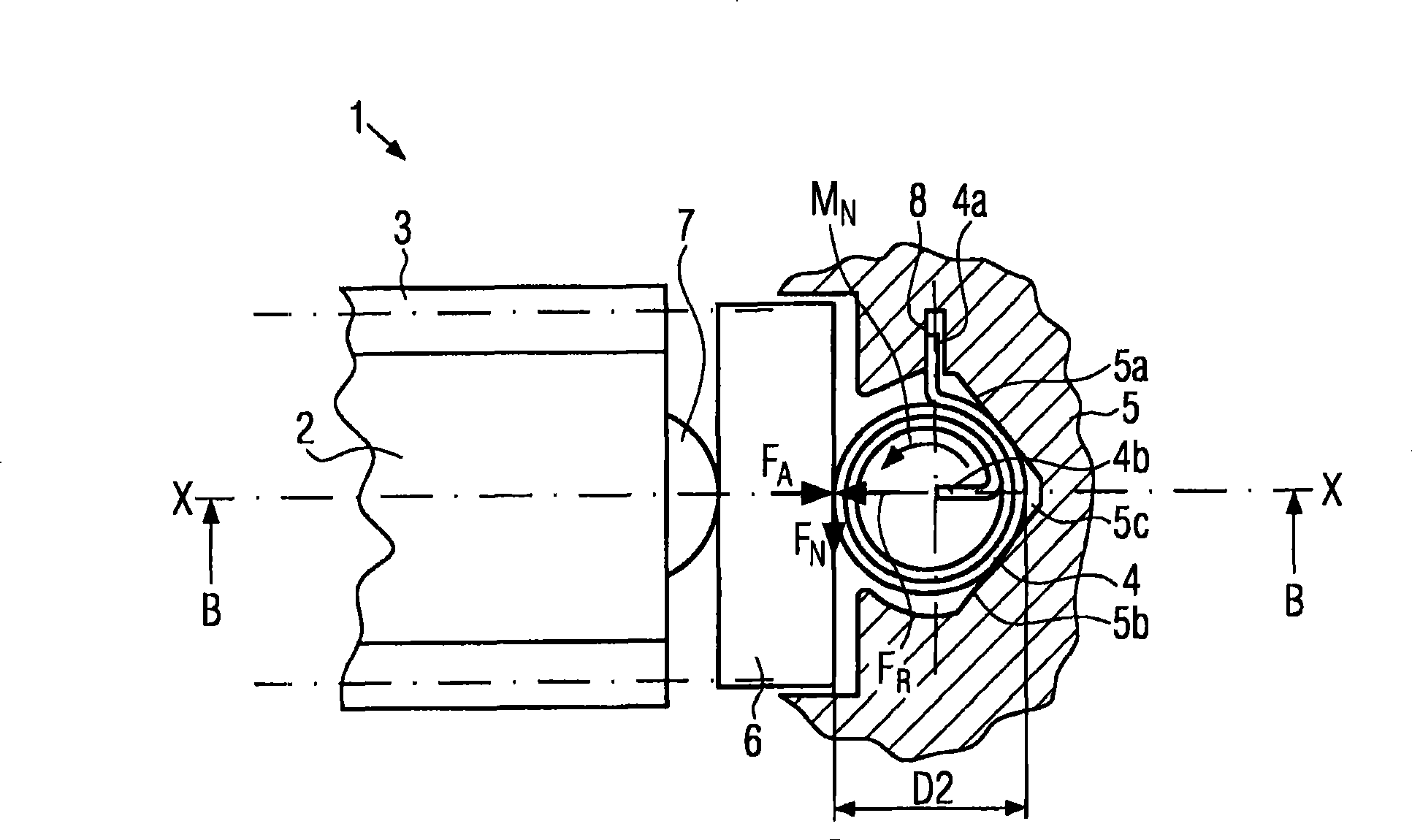
[0024] Refer below Figures 1 to 6 A transmission drive unit 1 according to a first embodiment of the invention will be described.

[0025] The transmission drive unit 1 comprises an electric motor with a shaft 2 on which a worm gear 3 is arranged. Here, shaft 2 is the armature shaft of the electric motor. As can be seen in particular from FIG. 2 , balls 7 or spherical axial projections are arranged on the end of the shaft, which can also be configured, for example, as domes and form point-shaped axial support.

[0026] The shaft 2 is arranged in a housing part 5 . In addition, in order to compensate the axial play of the shaft 2 , the compensating element 4 is arranged along the axial direction X-X of the shaft 2 . In this case, the compensating element 4 is arranged between the locking disk 6 and the housing part 5 at the end of the shaft 3 , which in this exemplary embodiment is formed by a ball 7 . The housing part 5 serves as a support part for the compensating eleme...


PUM


Abstract

The invention relates to a transmission drive unit which comprises a shaft (2) and a housing component (5), an adjusting element (4) for adjusting the axial backlash of the shaft (2) being arranged between one end of the shaft (2) and the housing component (5). The invention is characterized in that the adjusting element has a substantially cylindrical shape and can be expanded in the radial direction, when pretensioned, in order to enlarge an outer diameter, thereby allowing to exert a pretension (FR) onto the shaft (2) in the axial direction (X-X).

Description

technical field [0001] The invention relates to a transmission drive unit with axial play compensation for the axial play of a shaft. Background technique [0002] In order to prevent or adjust shaft axial play in servomotors or gears, for example spindle drives, axial forces occurring during operation can cause shaft play. However, this play should be suppressed as much as possible, wherein the axial play adjustment is preferably designed in such a way that it is available even with wear during the service life of the component. A transmission drive unit is known, for example, from DE 10 114 453 A1, in which axial play compensation of the shaft is effected by damping elements which are arranged on the outer circumference of the cup-shaped sleeve element. Here, the end of the shaft is positioned within the pot-shaped sleeve element. [0003] Other known solutions for compensating axial play are, for example, the provision of an adjusting screw which is arranged coaxially t...

Claims


Application Information

Patent Timeline
Patent Type & Authority Applications(China)
IPC IPC(8): F16H57/12F16H57/021
CPCF16F1/04F16H55/24F16H57/12F16C27/08F16C17/08F16H2057/0213F16C25/04Y10T74/19623F16H57/022F16H57/02
Inventor H-J·奥伯尔F·施文德曼
Owner ROBERT BOSCH GMBH
Why Eureka
Try Eureka