Method and system for producing multiple images in a single image plane using diffraction

An image and holographic image technology, applied in instruments and other directions, can solve problems such as expensive multi-laser hardware

Inactive Publication Date: 2009-02-11
布鲁斯哈
View PDF2 Cites 2 Cited by
  • Summary
  • Abstract
  • Description
  • Claims
  • Application Information

AI Technical Summary

Problems solved by technology

Additionally, the generation of these uniform phase interference dif

Method used


Image

  • Method and system for producing multiple images in a single image plane using diffraction
  • Method and system for producing multiple images in a single image plane using diffraction
  • Method and system for producing multiple images in a single image plane using diffraction

Examples


Embodiment Construction

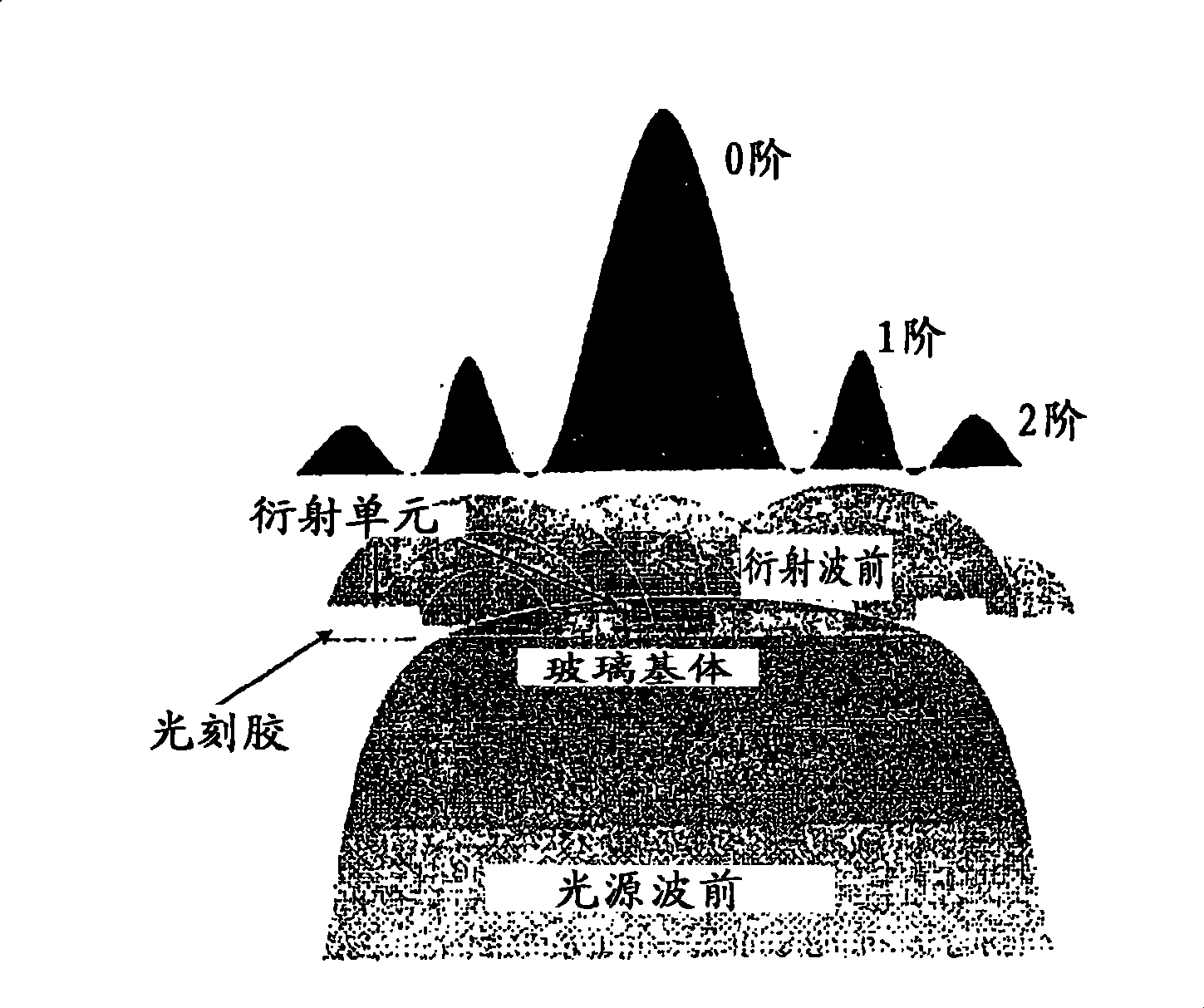
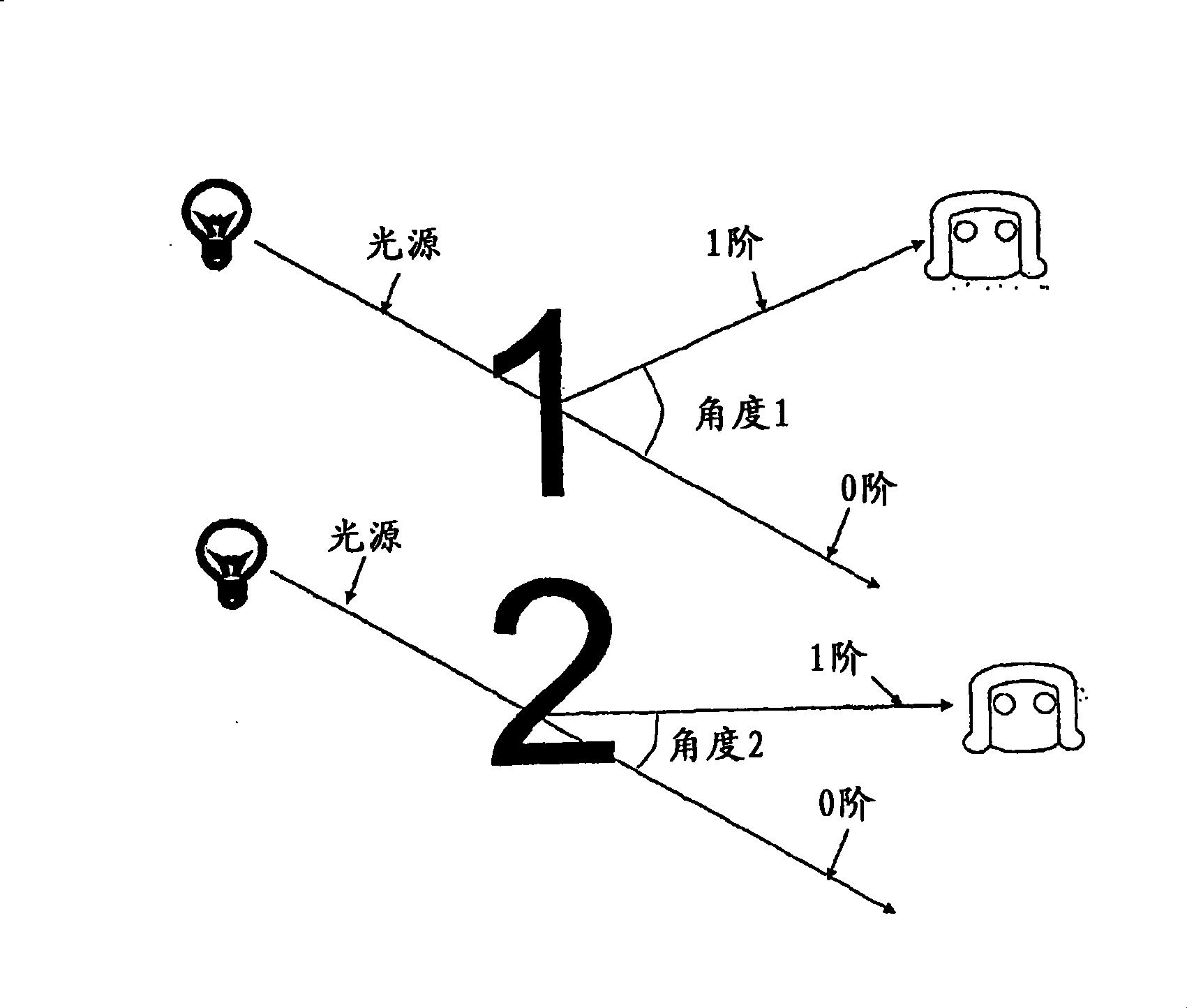
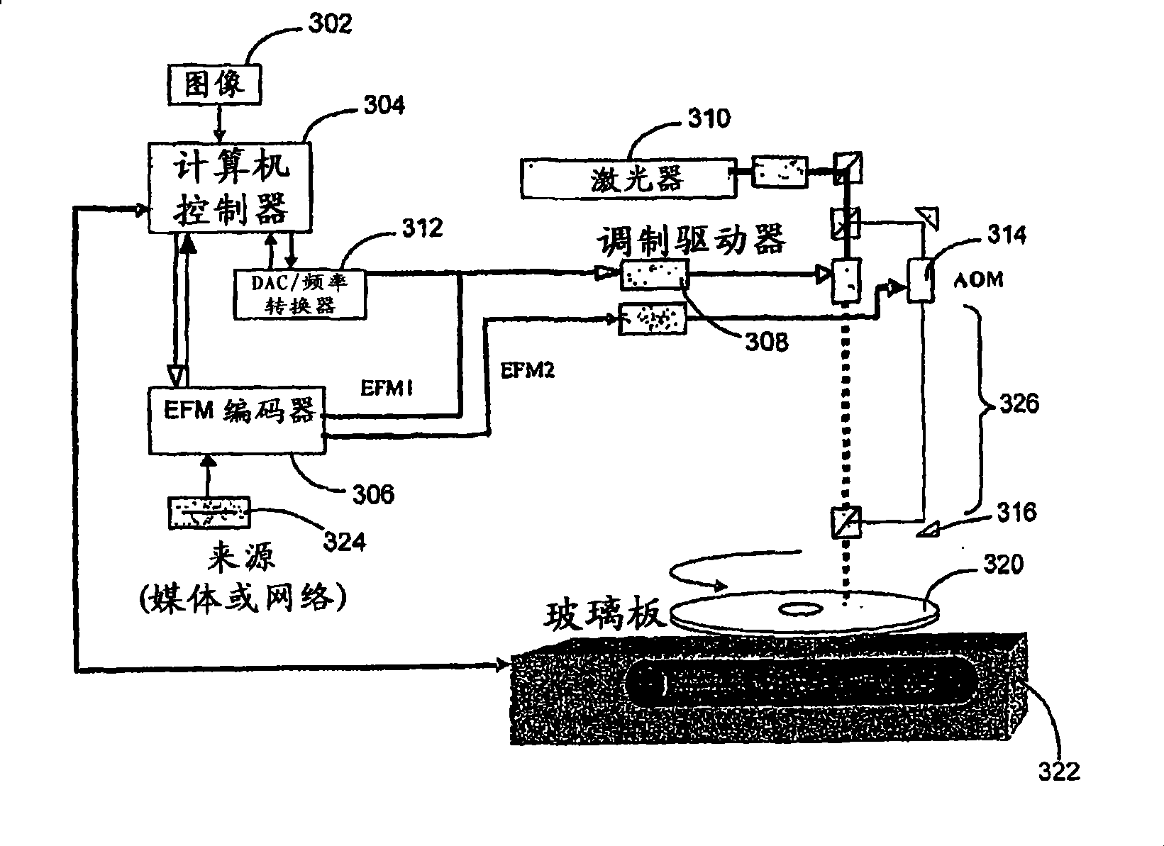
[0019] The present invention discloses a method for producing multiple diffraction images on a photosensitive substrate. These plurality of diffraction images comprise a plurality of diffraction elements visible at different angles with transmitted and / or reflected light. like figure 1 As shown in , these diffractive cells can be configured to reveal images designed to have a predominantly first order intensity. The invention can in turn be used to create a helical exposure pattern that matches the pixels of multiple images. The plurality of images may also be configured to be recorded at different concentrations and at different gratings within the photosensitive matrix.

[0020] In an exemplary embodiment, the first image and the integer spacing between each successive diffractive element are used together to generate a first set of diffractive elements with a first order intensity corresponding to a first angle, such as figure 1 shown in the illustration. Secondly, if ...


PUM

PropertyMeasurementUnit
Thicknessaaaaaaaaaa
Thicknessaaaaaaaaaa

Abstract

The present invention is directed to methods for creating pseudo-holographic images viewable under different selected angles on optical storage devices and other photosensitive surfaces. The present invention also discloses novel optical storage devices with super-imposed pseudo-holographic images. Generally, a photosensitive surface is exposed with multiple diffraction patterns creating super-imposed pseudo-holographic images. These diffraction patterns create super-imposed images on the photosensitive surfaces, which can be read by either a human or a computer.

Description

technical field [0001] The present invention relates to optical storage devices having superimposed pseudo-holographic images, and more particularly, the present invention relates to methods of producing pseudo-holographic images on optical storage devices and other photosensitive substrates, wherein the images are viewed at different selected angles. Visible. Background technique [0002] The creation of multiple distinct images on the same plane is currently possible with the aid of lens technology or holography. Lens technology relies on separating images by means of auxiliary lens sheets in order to differentiate the images. The images are interlaced and a lenticular sheet consisting of a series of cylindrical lenses molded into a plastic matrix is ​​laminated over the interlaced images. [0003] Holograms and optical interference are another way to distinguish multiple images on the same recording surface. In the case of a hologram, the purpose is to record the compl...

Claims


Application Information

Patent Timeline
IPC IPC(8): G03H1/04
Inventor 布鲁斯·哈
Owner 布鲁斯哈
Why Eureka
Try Eureka