Pneumatic tire

A pneumatic tire and tire circumferential technology, applied in heavy tires, tire parts, tire tread/tread pattern, etc., can solve the problems of uneven wear of heels and toes, wet skid resistance and uneven wear resistance, etc. problem, to achieve the effect of improving the edge effect

Inactive Publication Date: 2009-02-18
BRIDGESTONE CORP
View PDF1 Cites 13 Cited by
  • Summary
  • Abstract
  • Description
  • Claims
  • Application Information

AI Technical Summary

Problems solved by technology

However, as mentioned above, the pair of second ribs 111 are respectively divided into a plurality of divided ribs 117, and the shear deformation during kicking out becomes prone to uneven wear of heels and toes (hereinafter abbreviated as H&T). reason
For this reason, it is very difficult for conventional conventional pneumatic tires 101 to enhance wet skid resistance and uneven wear resistance.

Method used


Image

  • Pneumatic tire
  • Pneumatic tire
  • Pneumatic tire

Examples


Embodiment Construction

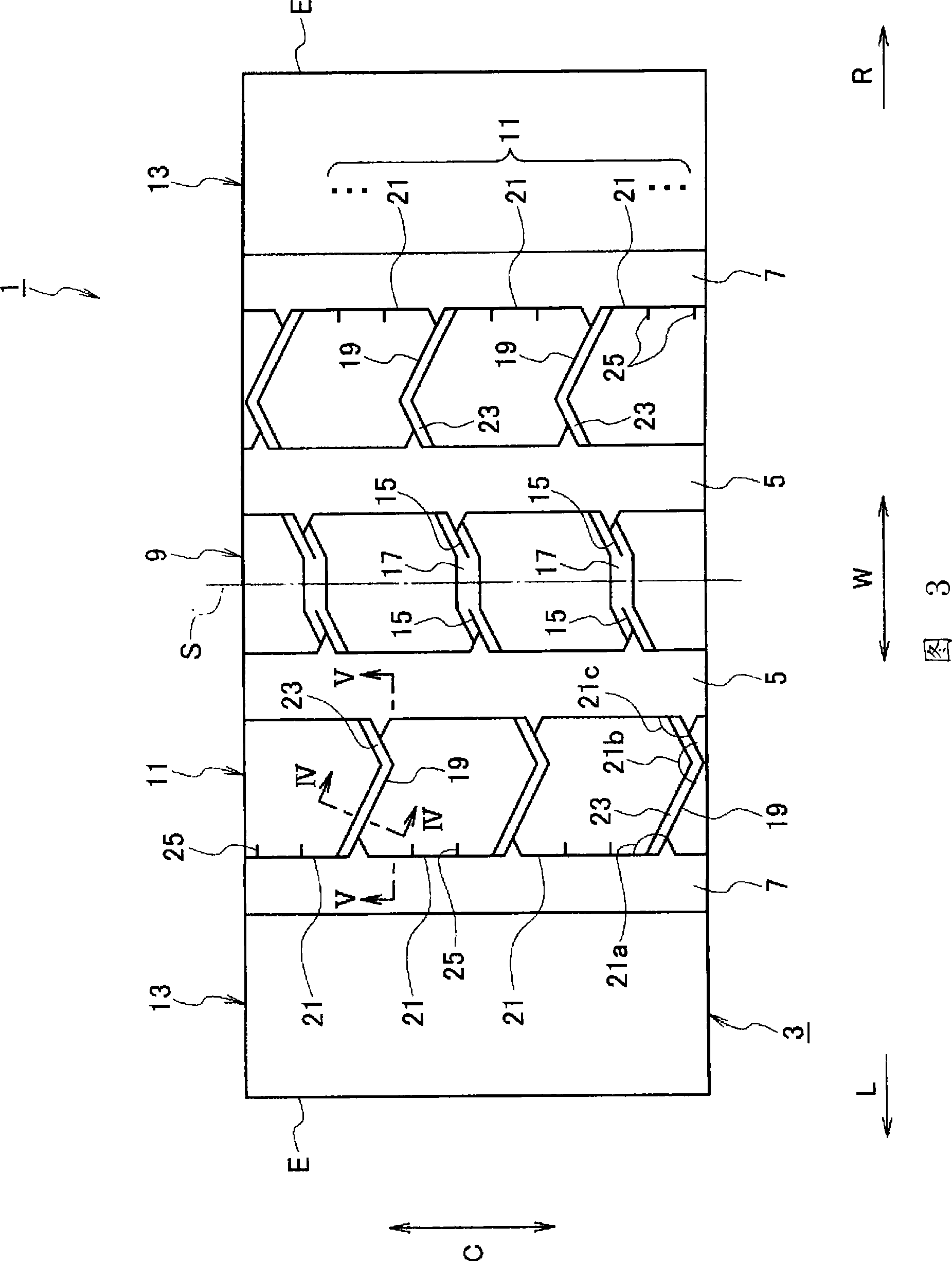
[0030] Refer to Figure 3 to Image 6 Embodiments of the present invention will be described.

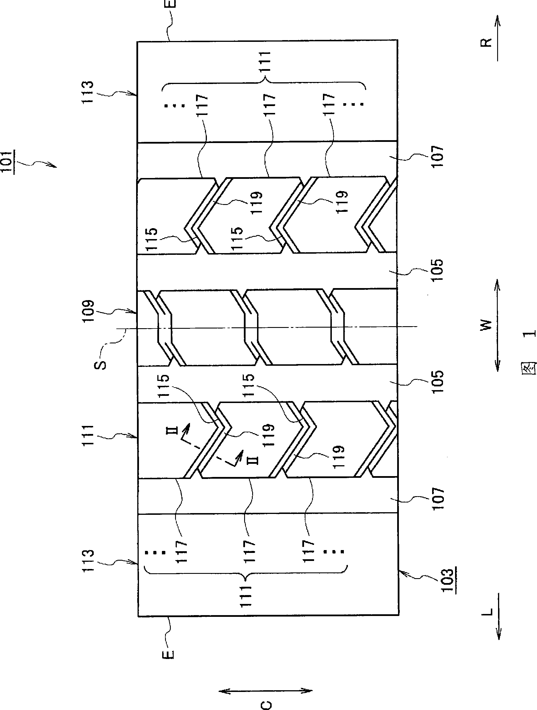
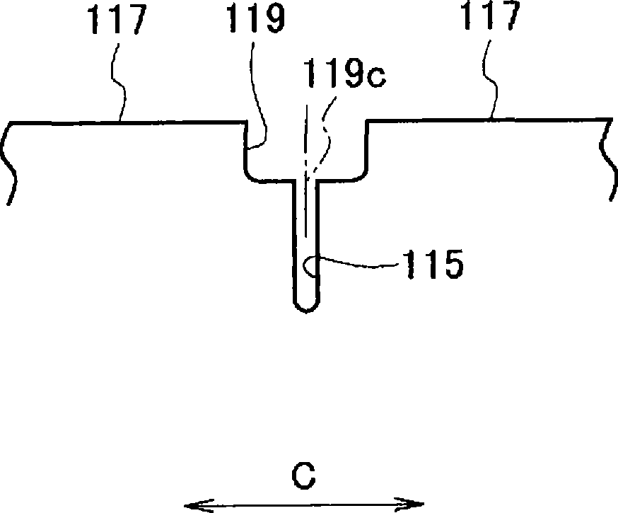
[0031] Here, FIG. 3 is a plan development view of a part of the tread of the pneumatic tire according to the embodiment of the present invention. Figure 4 It is a VI-VI sectional view of FIG. 3 . Figure 5 It is a V-V sectional view of FIG. 3 . Image 6 It is a figure which shows the other pattern of a sipe and a drain groove which concerns on embodiment of this invention. In addition, in the drawings, "L" indicates a leftward direction, and "R" indicates a rightward direction.

[0032] As shown in FIG. 3 , a pair of intermediate circumferential main grooves 5 continuously extending in the tire circumferential direction C are provided in the middle portion of the tread 3 of the pneumatic tire 1 according to the embodiment of the present invention, with the tire equator line S interposed therebetween. Further, a pair of shoulder circumferential main grooves 7 extending continuous...


PUM


Abstract

A plurality of ribs (9, 11, 13) extending in the circumferential direction (C) of the tire are sectioned by a plurality of main circumferential grooves (5, 7) in the width direction (W) of the tire. A plurality of sipes (19) are formed in two or more second ribs (11) at intervals in the circumferential direction (C) of the tire to traverse the tire. The two or more second ribs (11) are divided by the plurality of sipes (19) into a plurality of division ribs (21), respectively. All intersecting angular portions of each division rib (21) on one side in the circumferential direction (C) of the tire have obtuse angles. A hot water groove (23) communicating with the sipe (19) is formed to traverse the second rib (11) only on one side of each division rib (21) in the circumferential direction (C) of the tire.

Description

technical field [0001] The present invention relates to a pneumatic tire having both wet skid resistance and uneven wear resistance. Background technique [0002] Regarding the prior art, refer to Figure 1 and figure 2 Be explained. [0003] Here, FIG. 1 is a plan development view of a part of the tread of a pneumatic tire according to a conventional embodiment, figure 2 It is II-II sectional view of FIG. 1. In addition, in the drawings, "L" indicates a leftward direction, and "R" indicates a rightward direction. [0004] As shown in FIG. 1 , a pair of intermediate circumferential main grooves 105 extending in the tire circumferential direction C are provided on the middle portion of the tread 103 of the pneumatic tire 101 with the tire equator line S interposed therebetween. Further, a pair of shoulder circumferential main grooves 107 extending in the tire circumferential direction C are provided on the shoulder portion of the tread 103 with a pair of intermediate circu...

Claims


Application Information

Patent Timeline
Patent Type & Authority Applications(China)
IPC IPC(8): B60C11/04B60C11/12
CPCB60C11/1263B60C11/0306B60C11/125B60C11/04B60C2200/06
Inventor 本坊容一
Owner BRIDGESTONE CORP
Why Eureka
Try Eureka