Display method of emission display apparatus

A display method and luminous display technology, which is applied to static indicators, cathode ray tube indicators, instruments, etc., can solve the problems of display screen degradation, image retention, and resolution reduction, and achieve the effects of suppressing image retention and improving lifespan

Inactive Publication Date: 2009-02-25
CANON KK
View PDF2 Cites 35 Cited by
  • Summary
  • Abstract
  • Description
  • Claims
  • Application Information

AI Technical Summary

Problems solved by technology

However, there is no effect on the luminance that suppresses the deterioration of the pixel itself
In addition, an additional sensor is required for detecting brightness, resulting in increased production cost and reduced resolution
[0009] In an organic EL display, when the same still image is displayed for a long period of time, only a part of the display screen is degraded, causing image sticking
In addition, in an organic EL display having a plurality of sub-pixels with different emission wavelengths, color shift is caused in many cases because degradation characteristics are different for each emission color

Method used


Image

  • Display method of emission display apparatus
  • Display method of emission display apparatus
  • Display method of emission display apparatus

Examples


no. 1 example

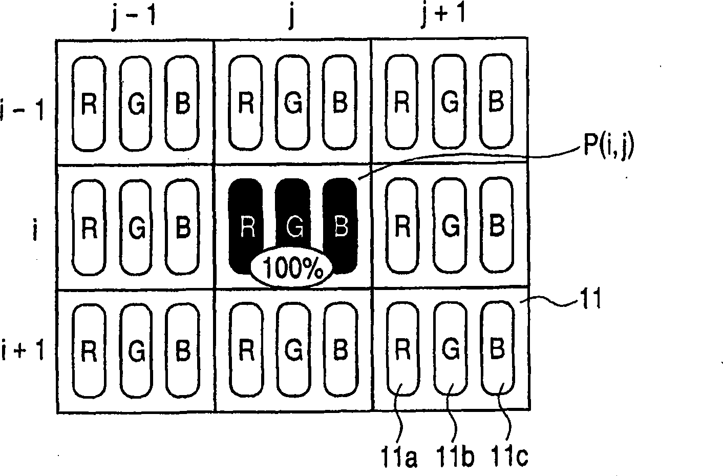
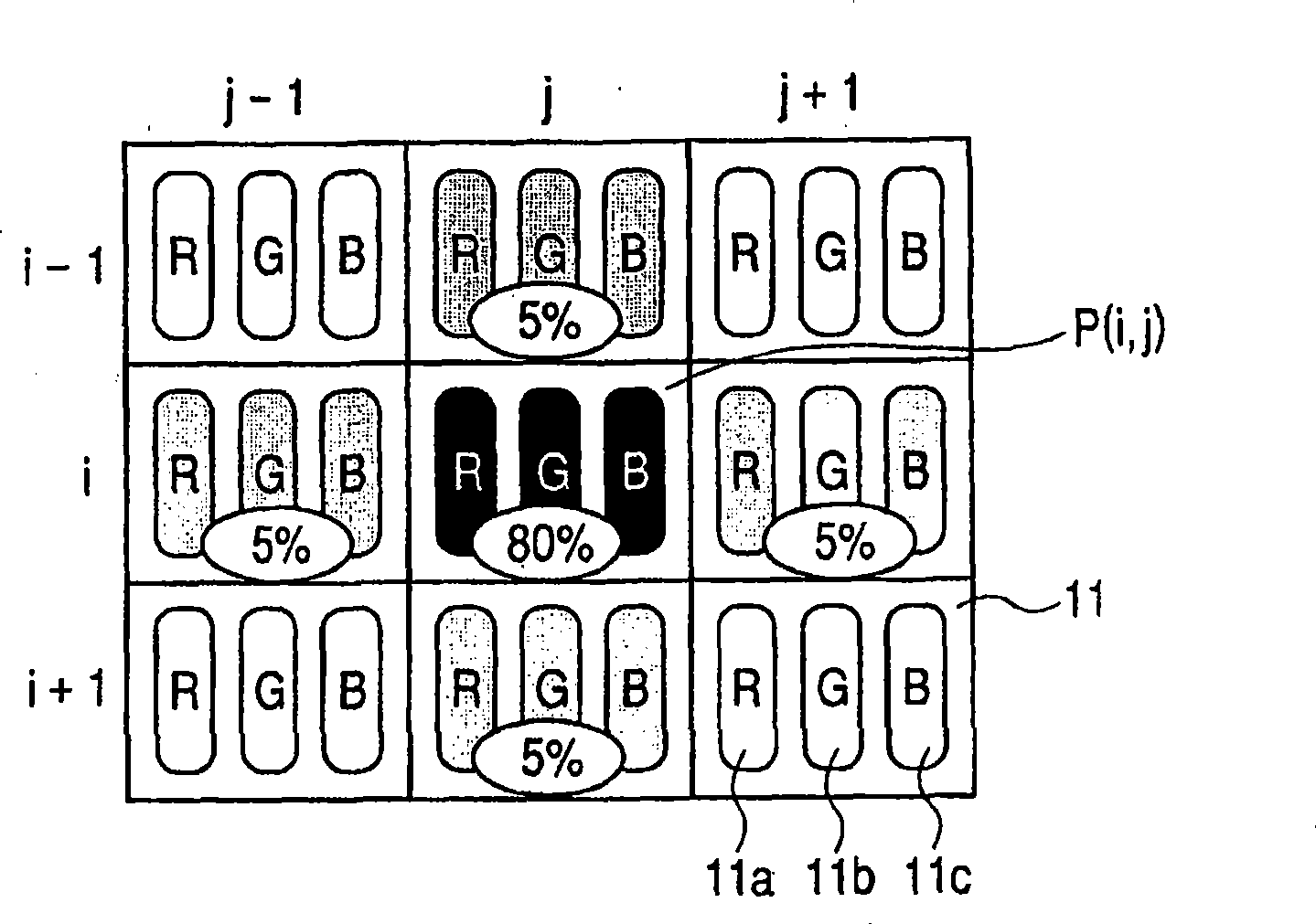
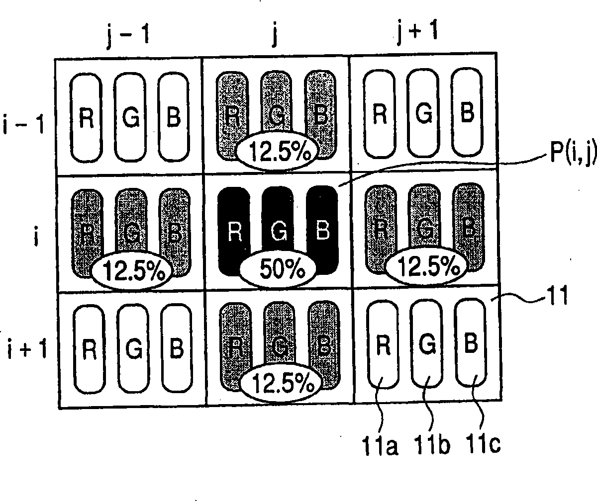
[0047] Figure 1 to Figure 15 are schematic diagrams each showing the pixel structure of the light-emitting display device used in the first embodiment of the present invention.

[0048] Such as Figure 1 to Figure 9 Each light-emitting display device shown in shows pixels 11 arranged in three rows and three columns (3×3). Each pixel includes an R sub-pixel 11a, a G sub-pixel 11b, and a B sub-pixel 11c. The coordinates in the vertical direction are indicated by "i", and the coordinates in the horizontal direction are indicated by "j". Execution with sub-pixel Sp a (i, j) corresponds to the image input data D a (i, j) display, sub-pixel Sp a (i,j) constitutes a pixel P(i,j) located at position (i,j) and has display color "a".

[0049] The term "sub-pixel Sp a (i, j)" refers to, for example, R sub-pixels, G sub-pixels or B sub-pixels constituting a pixel P(i, j). In addition, the term "adjacent pixel group P(i', j')" used here, for example Refers to the group consisting ...

no. 2 example

[0081] Next, a light emitting display device used in a second embodiment of the present invention is described. Figure 16 to Figure 1 8 is a schematic diagram showing the pixel structure of the light-emitting display device used in the second embodiment of the present invention.

[0082] Figure 16 shows the pixel structure in the high-resolution display mode, in which the image input data D is only displayed by the first display method a (i,j). The pixel structure has 3×3 pixels 11 . Each of the pixels 11 includes an R sub-pixel 11a, a G sub-pixel 11b, and a B sub-pixel 11c, respectively. The coordinates in the vertical direction are indicated by "i", and the coordinates in the horizontal direction are indicated by "j". Perform on sub-pixel Sp a Image input data D of (i,j) a (j, j) display, sub-pixel Sp a (i,j) constitutes a pixel P(i,j) located at position (i,j) and has display color "a".

[0083] In the case where the degradation characteristics of a plurality of s...


PUM


Abstract

Sticking of a Pixel is suppressed to improve the life of a display panel. In an emission display apparatus with a display panel in which a plurality of pixels each having at least one subpixel (11a, 11b, 11c) are disposed. A first display method of emitting light with only a pixel P(I,j) serving as an emission center and a second display method of allocating luminance of the pixel P(i,j) serving as an emission center to nearby pixels surrounding the pixel are combined in a controllable manner. A high-resolution mode with a high ratio of the first display method and a long-life mode with a high ratio of the second display method are switched therebetween depending on a spatial change or time change of image input data, an emission time, a degradation rate, a temperature, an emission luminance, and a display time.

Description

technical field [0001] The present invention relates to a display method of a light-emitting display device using an organic EL device, and more specifically, to a display method of a light-emitting display device characterized by a method of controlling a pixel structure. Background technique [0002] In a flat panel image display device (flat panel display) such as an organic EL display, when the same still image is displayed for a long period of time, a phenomenon called "sticking" occurs. The term "image sticking" used here means that only a part of the display screen deteriorates (decreases in luminance of light emission) to produce a visually recognizable residual image (afterimage). Image sticking tends to occur at edge portions and the like of still images. [0003] In an organic EL display having a plurality of sub-pixels of different emission wavelengths, there are many cases where degradation characteristics differ for each emission color. In addition, since the...

Claims


Application Information

Patent Timeline
Patent Type & Authority Applications(China)
IPC IPC(8): G09G3/30
CPCG09G5/10H10K59/35H10K71/70
Inventor 衣幡隼一福田浩一
Owner CANON KK
Why Eureka
Try Eureka