Method and apparatus for correcting audio signal

An audio signal and signal technology, which is applied in voice analysis, electrical components, instruments, etc., can solve problems such as discontinuous sound channels, inability to completely eliminate boundary effects, boundary effects, etc.

Inactive Publication Date: 2009-02-25
HUAWEI TECH CO LTD
View PDF0 Cites 14 Cited by
  • Summary
  • Abstract
  • Description
  • Claims
  • Application Information

AI Technical Summary

Problems solved by technology

[0012] However, MDCT coefficients inevitably produce quantization errors, which will affect the continuity between frames. Therefore, MDCT cannot completely eliminate the impact of boundary effects. When the signal changes sharply, especially after processing audio signals with strong energy The boundary effect is particularly obvious; and when dealing with multi-channel coding technology, redistribution of energy at the decoding end will make each channel discontinuous, resulting in more serious boundary effects

Method used


Image

  • Method and apparatus for correcting audio signal
  • Method and apparatus for correcting audio signal
  • Method and apparatus for correcting audio signal

Examples


Embodiment 1

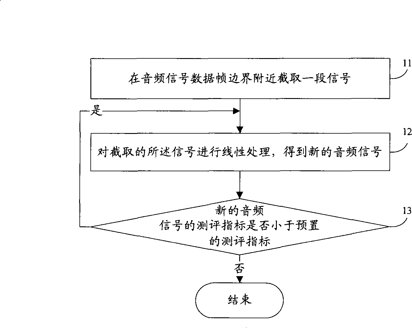
[0043] 101: Intercept a section of signal near the boundary of the audio signal data frame; for example, point X is the boundary point of signal 1, since the frame length of the general spectrogram is 256 points, start from point X to intercept 128 points forward and backward Intercept 128 points, and the intercepted 256 points form a frame signal;

[0044] 102: Perform LP (Linear Prediction, linear prediction) analysis on the intercepted signal to obtain the prediction coefficient, and then use the formula s ′ ( n ) = Σ i = 0 p a i s ( n - i ) Carry out linear prediction, and the obtained predicted value replaces the jump value near the data frame boundary to obtain a new audio signal;...

Embodiment 2

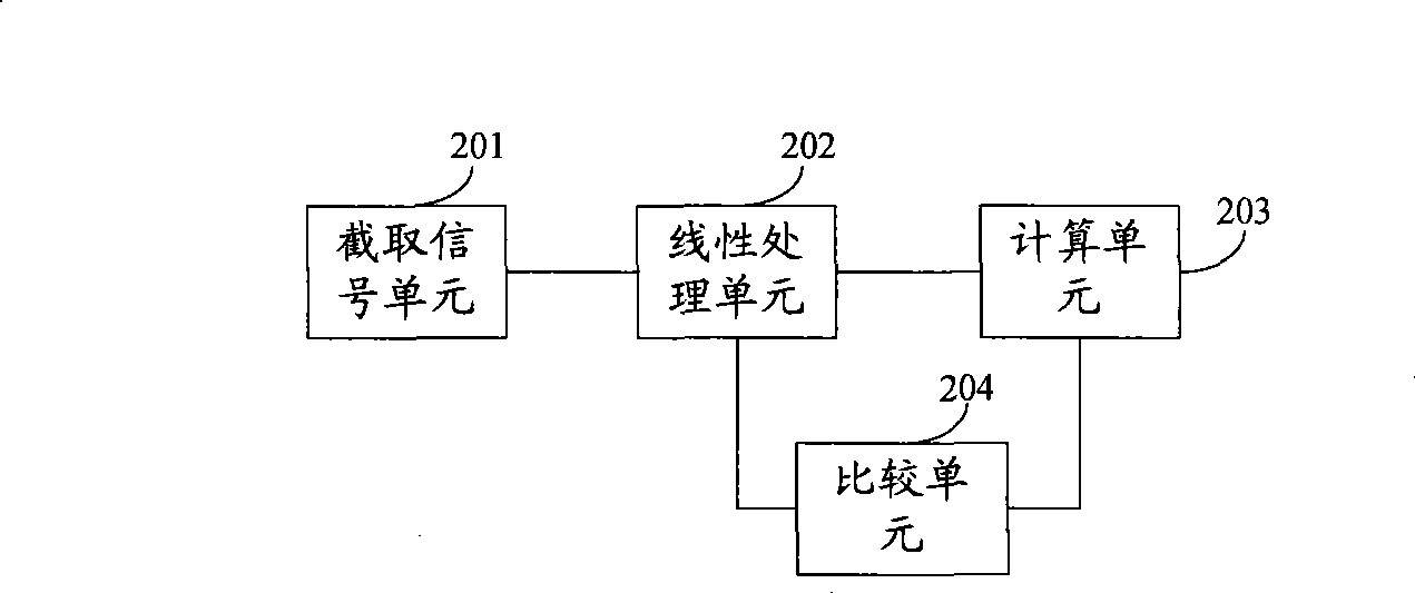
[0050]201: Intercept a section of signal near the boundary of the audio signal data frame; for example, point X is the boundary point of signal 1, since the frame length of the general spectrogram is 256 points, start from point X to intercept 128 points forward and backward Intercept 128 points, and the intercepted 256 points form a frame signal;

[0051] 202: Perform LP (Linear Prediction, linear prediction) analysis on the intercepted signal to obtain the prediction coefficient, and then use the formula s ′ ( n ) = Σ i = 0 p a i s ( n - i ) Carry out linear prediction, and the obtained predicted value replaces the jump value near the data frame boundary to obtain a new audio signal; ...

Embodiment 4

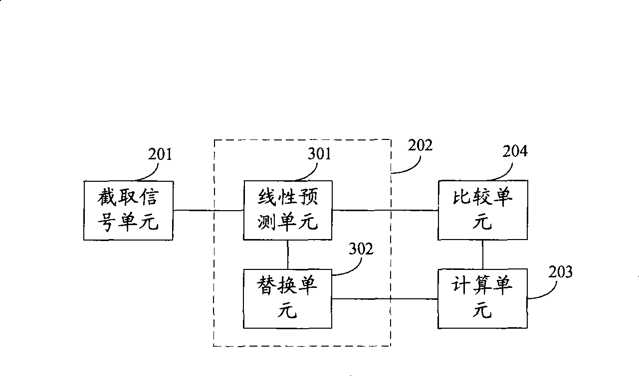
[0066] 401: Intercept a section of signal near the boundary of the audio signal data frame; for example, point X is the boundary point of signal 1, since the frame length of the general spectrogram is 256 points, start from point X to intercept 128 points forward and backward Intercept 128 points, and the intercepted 256 points form a frame signal;

[0067] 402: Perform LP (Linear Prediction, linear prediction) analysis on the intercepted signal to obtain the prediction coefficient, and then use the formula s ′ ( n ) = Σ i = 0 p a i s ( n - i ) Carry out linear prediction, and the obtained predicted value replaces the jump value near the data frame boundary to obtain a new audio signal;...


PUM


Abstract

The invention belongs to the technical field of communication, and discloses a method and a device for correcting audio signals. The method comprises the following steps: intercepting a segment of signal near the boundary of an audio signal data frame; subjecting the intercepted signal to linear treatment to obtain a new signal; and calculating the evaluation index of the new signal and, if the evaluation index is smaller than a preset evaluation index, continuing the linear treatment until the evaluation index of the signal after the linear treatment is larger than or equal to the preset evaluation index. The method has the advantages that the method has less calculation amount, can achieve smooth and periodic time domain waveforms of the audio signal by correcting the audio signal, and can ensure the phase information of the signal and reduce frequency spectrum divergence, thereby achieving smooth frequency spectrum and further eliminating boundary effect.

Description

technical field [0001] The invention relates to the field of communication technology, in particular to a method and device for correcting audio signals. Background technique [0002] Transform domain coding is one of the compression technologies commonly used in today's audio coding standards. It belongs to frequency domain coding. It reduces the correlation between components in the signal and quantizes and codes the transformed coefficients to achieve the purpose of information compression. Make full use of the auditory characteristics of the human ear in the frequency domain, such as masking effects and critical frequency bands, to achieve compression of audio signals. In practical applications, the audio signal is usually divided into several independent data frames for FFT (Fast Fourier Transform, Fast Fourier Transform) or DCT (Discrete Cosine Transform, Discrete Cosine Transform), but it cannot be guaranteed that each frame signal is continuous at the edge , and the...

Claims


Application Information

Patent Timeline
Patent Type & Authority Applications(China)
IPC IPC(8): G10L19/04G10L19/12H03M7/30
Inventor 郭利斌
Owner HUAWEI TECH CO LTD
Why Eureka
Try Eureka