Non-contact power supply, non-contact charger systems and method for charging rechargeable battery cell

一种非接触充电、非接触的技术,应用在电磁波系统、电池电路装置、传输系统等方向,能够解决不能次级线圈感应出感应电动势、充电效率取决位置关系、充电效率低等问题

Inactive Publication Date: 2009-02-25
LG CABLE LTD (KR)
View PDF8 Cites 75 Cited by
  • Summary
  • Abstract
  • Description
  • Claims
  • Application Information

AI Technical Summary

Problems solved by technology

[0006] However, the above-mentioned conventional non-contact charging system has a disadvantage in that the charging efficiency depends on the positional relationship between the primary coil and the secondary coil
That is, in the case where there is a positional deviation between the primary coil and the secondary coil, the induced electromotive force cannot be sufficiently induced in the secondary coil, so the charging efficiency of this non-contact charging system is lower than that of the contact charging system. Low

Method used


Image

  • Non-contact power supply, non-contact charger systems and method for charging rechargeable battery cell
  • Non-contact power supply, non-contact charger systems and method for charging rechargeable battery cell
  • Non-contact power supply, non-contact charger systems and method for charging rechargeable battery cell

Examples


Embodiment Construction

[0033]Preferred embodiments of the present invention will be described in detail below with reference to the accompanying drawings. Before the description, it should be understood that the terms used in this specification and the appended claims should not be interpreted as being limited to the meaning of the general dictionary, but should be based on the principle of allowing the inventor to properly define the terms for the best interpretation, according to the present invention The corresponding meanings and concepts of the technical aspects are explained. Therefore, the descriptions presented here are preferred embodiments for illustrative purposes only, and are not intended to limit the scope of the present invention, so it should be understood that other equivalents and modifications can be made thereto without departing from the spirit and scope of the present invention. .

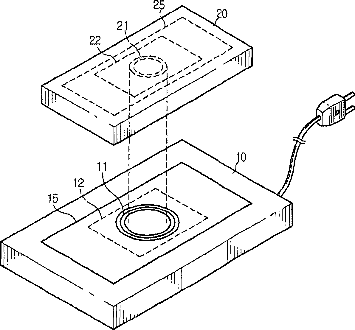
[0034] figure 1 It is a schematic perspective view of a conventional non-contact charging syst...


PUM


Abstract

The present invention relates to a contact-less power supply magnetically coupled to a battery device having a receiving coil therein, for contact-less charging the battery device, the contact-less power supply having a sending coil array including a plurality of sending coils for inducing a charging power to the receiving coil; and a driving means for detecting a sending coil magnetically coupled to the receiving coil and selectively driving only the detected sending coil.

Description

technical field [0001] The present invention relates to power supplies for portable electronic devices, and more particularly, to contactless charging systems utilizing inductive coupling. Background technique [0002] Rechargeable secondary batteries are installed in portable electronic devices such as mobile communication terminals, PDAs, and the like. To charge the secondary battery, a separate power source is required to power the battery of the portable electronic device using household commercial power. Typically, the power supply and the battery each have separate external contact terminals whereby the power supply and the battery are electrically connected by connecting the two contact terminals. [0003] However, if the contact terminals protrude outward, the aesthetic appearance will be spoiled, and the contact terminals will be contaminated by external impurities, resulting in poor contact state. Also, the battery is prone to lose charged energy if the user acci...

Claims


Application Information

Patent Timeline
Patent Type & Authority Applications(China)
IPC IPC(8): H02J17/00H01F38/14H02J7/00
CPCH02J7/025H02J50/90H02J7/00304H02J7/00308H02J50/10H02J50/40H04B5/24H04B5/79
Inventor 崔星旭权光熙金政范文盛煜朴东荣韩燮
Owner LG CABLE LTD (KR)
Why Eureka
Try Eureka