Interface for coupling an array of coils to a magnetic resonance imaging system

a magnetic resonance imaging and array technology, applied in the field of peripheral vasculature imaging methods and apparatuses, can solve the problems of limited field of view, relative insensitivity of remote coils to individual spins, and trade-off between resolution

Inactive Publication Date: 2005-05-03
BAYER HEALTHCARE LLC
View PDF5 Cites 41 Cited by
  • Summary
  • Abstract
  • Description
  • Claims
  • Application Information

AI Technical Summary

Problems solved by technology

Because of their large size the remote coils suffer from a relative insensitivity to individual spins.
A disadvantage of the surface coil however, is its limited field of view.
Therefore, the surface coil necessarily restricts the field of view and inevitably leads to a tradeoff between resolution and field of view.
Generally, larger coils induce greater patient sample losses and therefore have a larger noise component, while smaller coils have lower noise but in turn restrict the field of view to a smaller region.
While an increased number of surface coils may be used to increase the field of view, NMR system scanners typically have a limited number of preamplifier inputs.
The number of preamplifier inputs is therefore a design limitation in the design of phased array surface coils.
A disadvantage of known phased array surface coils, therefore, is that e surface coil array may include only as many coils as can be directly connected to the preamplifiers of the system scanner.
This technique however, requires excessive scan room intervention.
That is, after each scan, a technician enters the scan room to physically re-position the coils This may increase examination time and increase the likelihood of a patient rejecting the procedure.

Method used


Image

  • Interface for coupling an array of coils to a magnetic resonance imaging system
  • Interface for coupling an array of coils to a magnetic resonance imaging system
  • Interface for coupling an array of coils to a magnetic resonance imaging system

Examples


Embodiment Construction

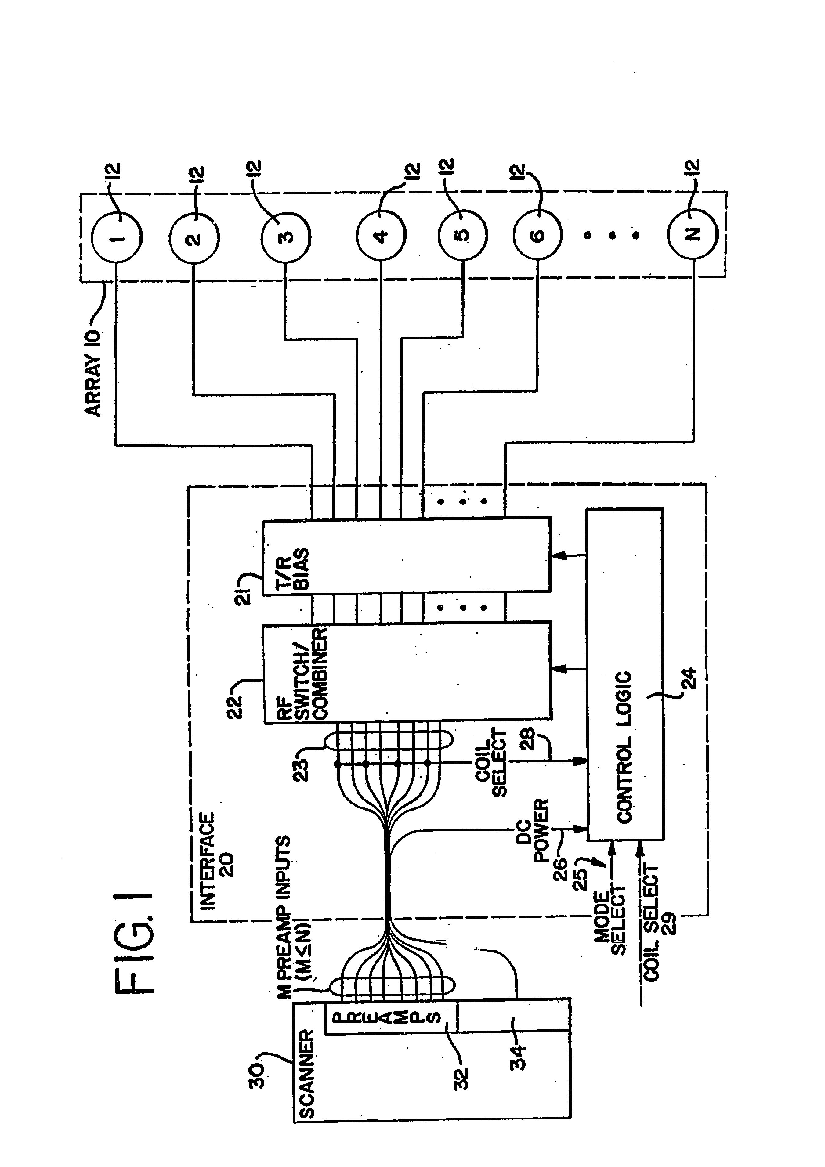
[0025]FIG. 1 is a schematic diagram of a system for receiving an NMR response signal in accordance with a preferred embodiment of the present invention. The system includes a surface coil array 10 that is connected by an interface 20 to an NMR scanner 30. The surface coil array 10 includes a number, N, of surface coils 12. Each of the surface coils 12 is electrically connected through a transmit / receive (“T / R”) bias circuit 21 to an RF switch / combiner 22 in the interface 20. The RF switch / combiner 22 has a plurality of outputs 23 that are connected to a plurality of receiver preamplifiers 32 in the NMR scanner 30.

[0026]The interface 20 also includes a control logic circuit 24, which is coupled to and controls the RF switch / combiner 22 and the T / R bias 21. The control logic circuit 24 has three inputs. The first input is a DC power input 26, which is provided by a power supply 34 in the NMR scanner 30. The second input is a coil select input 28. The third input is a mode select input...


PUM


Abstract

A coil interface is capable of coupling an array of coils to a magnetic resonance (MR) system. The MR system is equipped with a predetermined number of receivers. The coil interface includes a plurality of input ports, a plurality of output ports, and an interface circuit disposed therebetween. The plurality of input ports is used to couple the interface circuit to the coils of the array. The plurality of output ports is used to couple the interface circuit to the receivers of the MR system. The interface circuit is used to selectively interconnect at least two of the input ports to at least one of the output ports, thereby allowing the array of coils to be selectively operated in any one of a plurality of operational modes.

Description

CROSS-REFERENCE TO RELATED APPLICATIONS[0001]This application for patent is continuation of U.S. application Ser. No. 10 / 015,190, filed Nov. 26, 2001, now U.S. Pat. No. 6,714,012 which itself is a divisional of U.S. application Ser. No. 08 / 978,718, filed Nov. 26, 1997, now issued as U.S. Pat. No. 6,323,648 on Nov. 27, 2001. This application thus claims the benefit of the filing date of the great-grandparent application, Nov. 26, 1997.BACKGROUND OF THE INVENTION[0002]The present invention relates to nuclear magnetic resonance (“NMR”) imaging and, more particularly, to methods and apparatus for imaging the peripheral vasculature.[0003]Initially, NMR imaging systems utilized receiver coils which surrounded the entire sample (for example a human patient) that was to be imaged. These remote coils had the advantage that the sensitivity was, to a first approximation, substantially constant over the entire region being imaged. While this uniformity in sensitivity is not strictly characteris...

Claims


Application Information

Patent Timeline
Patent Type & Authority Patents(United States)
IPC IPC(8): G01R33/34G01R33/3415G01V3/00
CPCG01R33/3415
Inventor BELT, KENNETH W.REICHEL, MICHAELWATRAL, J. MICHAEL
Owner BAYER HEALTHCARE LLC
Why Eureka
Try Eureka