Linear faraday induction generator for the generation of electrical power from ocean wave kinetic energy and arrangements thereof

a technology of wave kinetic energy and generator, which is applied in the direction of electric generator control, machines/engines, magnetic bodies, etc., can solve the problems of extreme violent and undesirable standing waves, wave energy is reflected, and wave energy is dissipated, so as to achieve the effect of dissipating the mechanical energy of waves

Active Publication Date: 2014-05-01
SLP CONSULTANTS INC
View PDF5 Cites 43 Cited by
  • Summary
  • Abstract
  • Description
  • Claims
  • Application Information

AI Technical Summary

Benefits of technology

[0032]Another embodiment is directed to an electrokinetic seawall system comprising a plurality of wave energy converters (WECs). Each of the WECs includes a buoyant portion configured to be disposed above a surface of a fluid medium when the WEC is immersed in the fluid medium. In addition, each of the WECs is configured to convert mechanical energy of waves traversing the fluid medium into an electrical current. Further, the plurality of WECs are affixed such that distances between adjacent WECs of the plurality of WECs are at most 8 times a height of one of the buoyant portions to dissipate the mechanical energy of the waves over an area of the fluid medium.
[0034]Another embodiment is directed to a wave energy converter system including a buoyant rotor, a stator and an inertial wave dampening mechanism. The rotor is configured to be driven by waves traversing a fluid medium. In addition, the stator is configured to be at least partially submerged in the fluid medium and to be relatively stationary with respect to the rotor in response to the waves. Further, the inertial wave dampening mechanism is attached to the stator and comprises a weight container including at least one ingress hole configured to draw the fluid medium into the container to thereby attain sufficient weight to stabilize and render the stator relatively stationary in response to the waves.

Problems solved by technology

In either case, the waves collide violently with the seawall, which then dissipates the wave energy through frictional losses into useless heat.
Seawalls of the first type suffer from the problem that some of the wave energy is reflected producing extremely violent and undesirable standing waves in front of the seawall.
Seawalls of the second type, developed to avoid the standing wave problem, suffer from the fact that the curved exposed surface suffers from increased cumulative damage with shortened lifespan as that type of seawall has to absorb all of the wave energy rather than reflecting a portion of it back toward the ocean in the direction of the original wave propagation.
In either case, tremendous amounts of energy is wasted and lost as frictional heat and turbulence.
With existing technology, however, only about 0.5 TW could in theory be captured.
The process of a wave impinging upon a coastline causes all of its stored energy to be released as frictional heat resulting in the undesirable effects to the coastline.
These waves carry the greatest amount of energy and are the most harmful to beaches, coast lines, and the life expectancies of seawalls.
Storm waves of great height will destroy such wave energy dissipating devices.
Also, even if the device has excellent survivability, the efficiency of the device will go down drastically if the waves impacting upon it are significantly higher than the height with which the device was designed operate.

Method used


Image

  • Linear faraday induction generator for the generation of electrical power from ocean wave kinetic energy and arrangements thereof
  • Linear faraday induction generator for the generation of electrical power from ocean wave kinetic energy and arrangements thereof
  • Linear faraday induction generator for the generation of electrical power from ocean wave kinetic energy and arrangements thereof

Examples


second embodiment

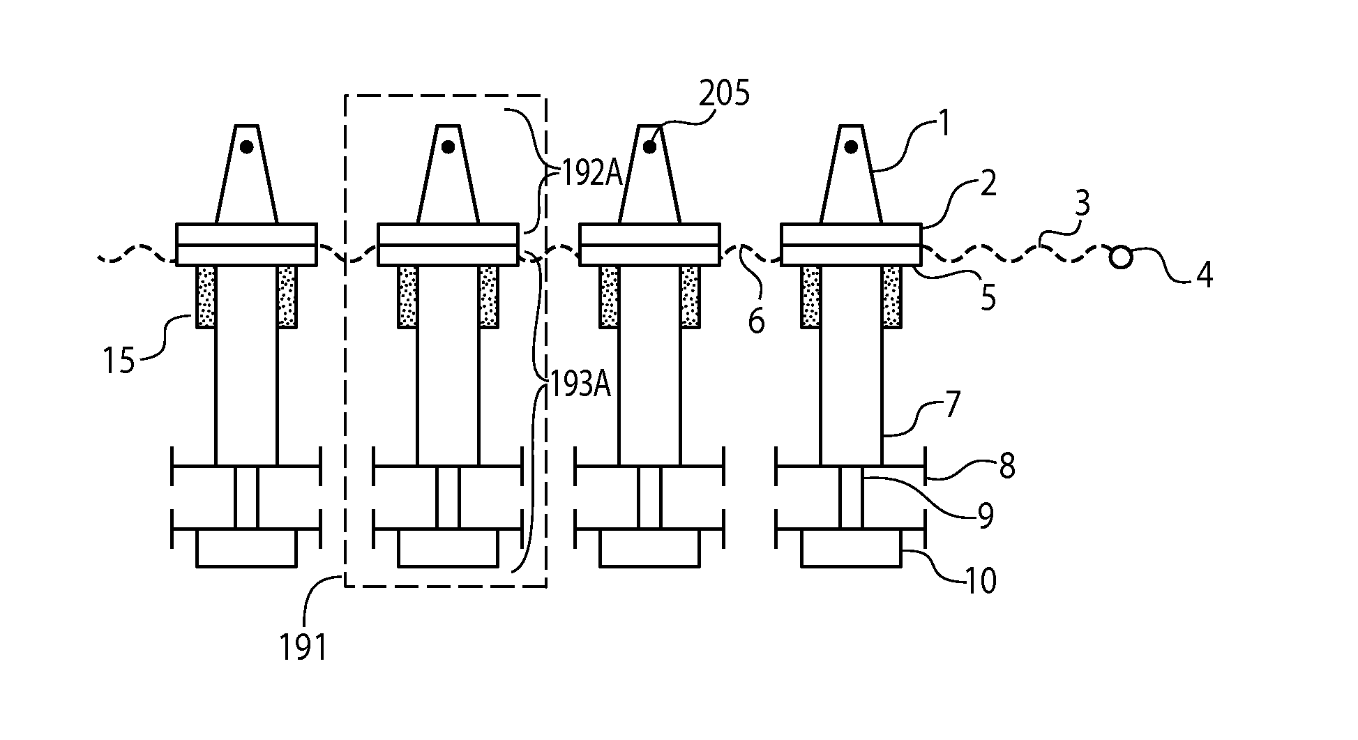
[0157]While both embodiments of the VLEG are functionally equivalent, the preferred embodiment is for the rotor being the PMA and the FCA being the stator for two important reasons: 1) It can be shown mathematically that the kinetic energy transferred and developed in the rotor is proportional to the mass of the rotor. Thus, the mass of the rotor should be made as large as possible consistent with the ratio of the mass of the mobile submit to the fixed subunit being as small as possible. 2) There are many wire connections that are made between the many coils and the power collection circuitry (PCC). To connect many moving coils with moving wires to a fixed positioned PCC (even allowing for the fact that some of the PCC could be fixed to the FCA rotor itself) would produce serious reliability problems from wire and metal vibrational fatigue and eventual breakage in the rugged environment of the ocean. However, in certain circumstances the second embodiment with a stationary PMA and m...

first embodiment

[0158]Also, with the preferred arrangement, to ensure that a given amount of kinetic energy imparted to the rotor is efficiently converted to electrical energy, there should be two coils in the FCA for every magnet in the PMA or 4 coils for every magnet pair, and the combined width of these four coils should equal approximately the length of two magnet thicknesses plus two pole pieces to ensure that a coil would not be over significant amounts of S and N directed magnetic field lines simultaneously which would seriously degrade efficiency and power output except briefly when a given coil would be over the precise center of a magnet's longitudinal thickness. If the thickness of the power producing magnet is Tm and the thickness of the pole piece is Tp, then the width of each of the four coils should be, in the preferred configuration, approximately (Tm+Tp) / 2. This preferred configuration is most efficacious when the amplitudes of the incoming waves are relatively small, as is with ca...


PUM


Abstract

Various embodiments of linear electric generators and arrangements thereof are disclosed. One such generator includes a permanent magnetic array with magnets that are oriented such that like poles of the magnets are disposed adjacently to concentrate a magnetic field through a coil array. To enhance the magnetic field distribution, the magnets are affixed under a compressive strain due to repulsive forces resulting from proximity of the like poles. According to another aspect, a plurality of vibrational linear electric generators (VLEGs) can be arranged so that magnets of different VLEGs are oriented so that poles of opposite polarity are disposed adjacently to further enhance magnetic field concentration through coil arrays. In addition, a plurality of wave energy converters can be arranged in very close proximity, at most 8 times a height of a buoyant portion of the converters, to act as a seawall and thereby protect various structures from ocean waves.

Description

RELATED APPLICATION DATA[0001]This application is a Divisional application of co-pending U.S. patent application Ser. No. 13 / 662,630 filed on Oct. 29, 2012, incorporated herein by reference in its entirety.[0002]This application is also related to commonly owned application Ser. No. ______ (Attorney Docket Number 634-2 (DIV 2), filed concurrently herewith and incorporated herein by reference.BACKGROUND[0003]1. Technical Field[0004]The present principles are directed to linear faraday induction generators as well as electrokinetic seawall apparatuses that employ linear faraday induction generators to dissipate ocean wave kinetic energy.[0005]2. Description of the Related Art[0006]Seawalls are widely used to protect fragile beaches, coastline, and coastal structures from the enormous power and energy of ocean waves and to provide areas of calm water for shipping and recreational purposes. Waves impact upon a seawall, of which there are basically two principal types—type 1 seawalls of ...

Claims


Application Information

Patent Timeline
Patent Type & Authority Applications(United States)
IPC IPC(8): F03B13/18
CPCF03B13/16H02K7/1876F05B2220/707H01F7/0273Y02E10/38F03B13/1855H02K35/02F05B2240/40Y02E10/30F03B13/188H02K35/00H02K2203/00H02M7/064H02M7/066
Inventor PHILLIPS, REED E.
Owner SLP CONSULTANTS INC
Why Eureka
Try Eureka