In another embodiment of the invention, the pusher
electrode surface, consisting of an array of independent electrodes which are powered to create a high-frequency
electric field and form a pseudo potential barrier near the pusher
electrode surface, is coated or manufactured at the surface with material selected to minimize
charge exchange when an ion impacts the surface. In some applications, the pusher
electrode surface can be heated to reduce the probability of ions being retained at the surface upon colliding and / or fragmenting. Surface materials that minimize
charge exchange will improve ion yield in both SID and in energy-absorbing low
impact energy collisions, resulting in higher TOF sensitivity in both cases. In addition to the array of high-frequency electrodes that form the pseudo potential barrier near the pusher electrode surface, the pusher electrode
assembly can be comprised of multiple electrode segments with different voltages applied to each segment. Voltages can be applied to a multiple segment electrode during ion collection to help prevent ions from leaving the pseudo potential well in directions normal to the well depth axis, that is, parallel to the pusher plate surface. Additional electrodes can also be configured at the periphery of the acceleration region to generate potentials that constrain ions in directions normal to the pseudo potential well axis. Such fields can be configured advantageously to reduce the
spatial distribution of ions in these directions normal to the potential well axis. This results in a reduction of the effects of field distortions in the TOF
optics, such as from: deflection fields;
edge effects, that is, field distortions due to the
mechanical design at field boundaries; and geometrical inaccuracies, such as from mechanical misalignments.
In yet another embodiment of the invention, ions are created in the pulsing region of a Time-Of-Flight
mass analyzer while maintaining a substantially neutral field between the two electrodes of the pulsing region. The resulting ion
population is subsequently directed to a pseudo potential well near the pusher electrode, created by the application of high-frequency potentials to an array of independent electrodes in the surface of the pusher electrode, prior to pulsing of the ions into the Time-Of-Flight drift region. A specific example of such an embodiment of the invention is the configuration of an
Electron Ionization (EI) source in the pulsing region of the Time-Of-Flight
mass analyzer. Sample bearing gas is introduced at low pressure into the pulsing region of a Time-Of-Flight
mass analyzer with a neutral electric field applied across the pulsing region gap. An
electron-emitting filament is turned on with the emitted electrons accelerated into the pulsing region gap to ionize the
gas phase sample present. The
electron-emitting filament is turned off and a reverse electric field is applied across the pulsing region gap to direct the gaseous ions produced to move toward a pseudo potential well near the pusher electrode. When the EI generated ions have been collected in the pseudo potential well near the pusher electrode, an accelerating field is applied across the pulsing region gap to accelerate the ions into the drift region of the Time-Of-Flight mass analyzer. The EI generated ions can initially be directed toward the pseudo potential well near the pusher electrode with sufficient energy to
impact the pusher electrode surface and cause surface induced dissociation, or with low energy to allow non-fragmenting collisions that dissipates ion
kinetic energy. The sample gas may be supplied from a variety of inlet systems including but not limited to a gas chromatograph. Collecting EI generated ions in a pseudo potential well and cooling them by allowing collisions with the pusher surface, or with the introduction of collision gas, prior to pulsing into the Time-Of-Flight drift region reduces the ion
kinetic energy distribution and spatial spread. This results in higher resolving power and mass accuracy Time-Of-Flight mass to charge analysis. If
electron ionization occurs in the presence of the pseudo potential well distribution, the ratio of
ionization time to TOF
ion acceleration and
flight time can be increased resulting in higher overall Time-Of-Flight
duty cycle.
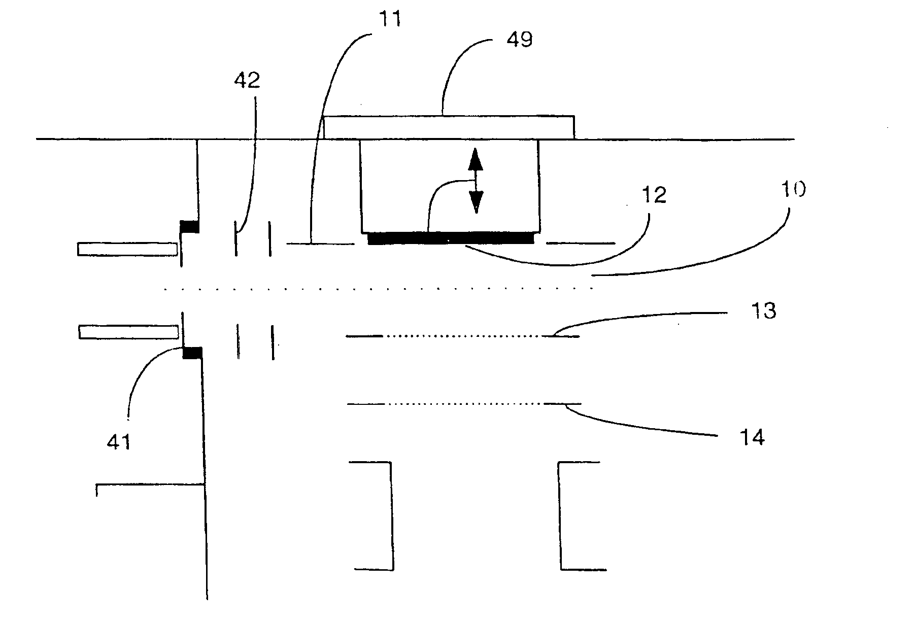
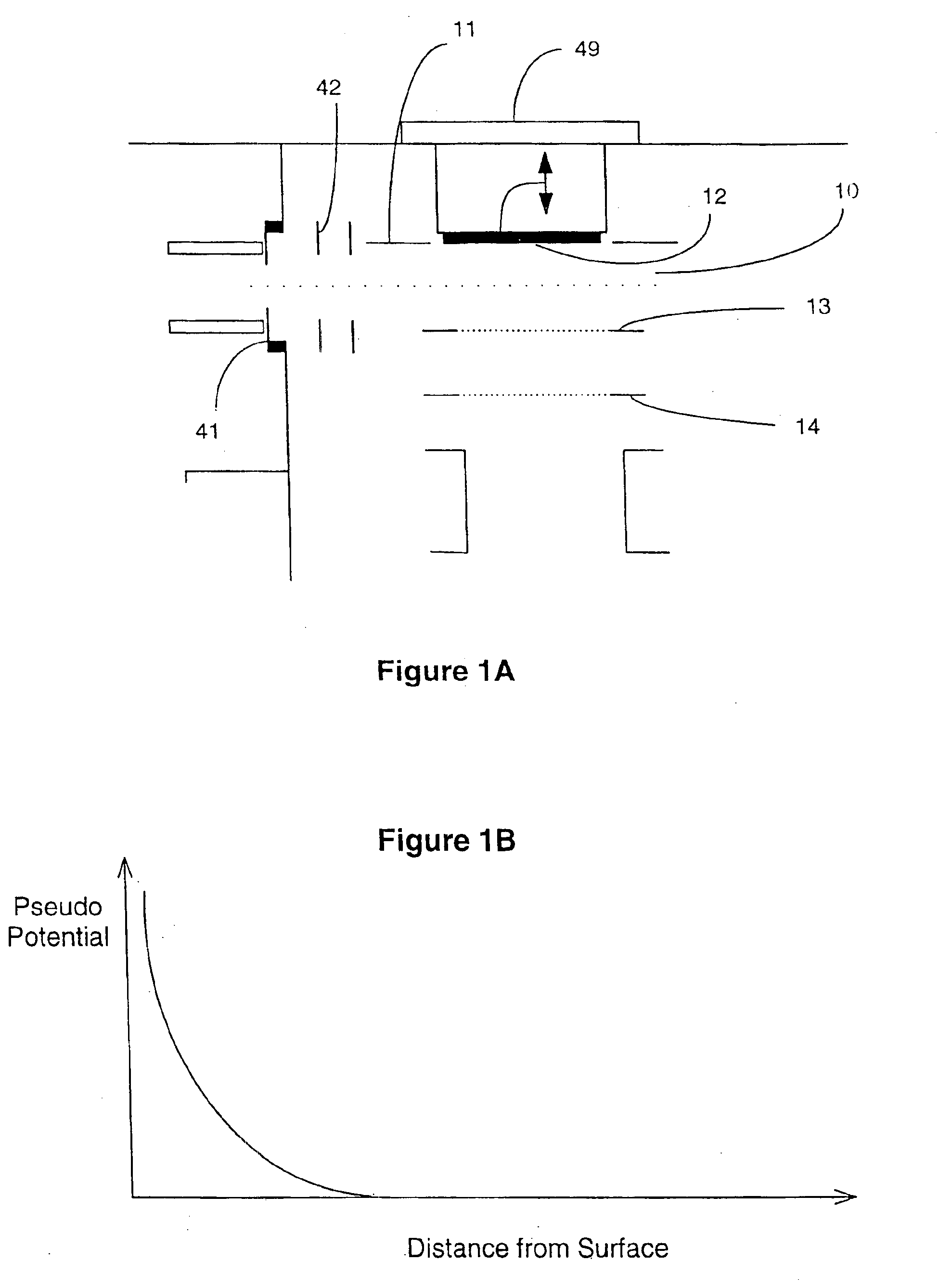
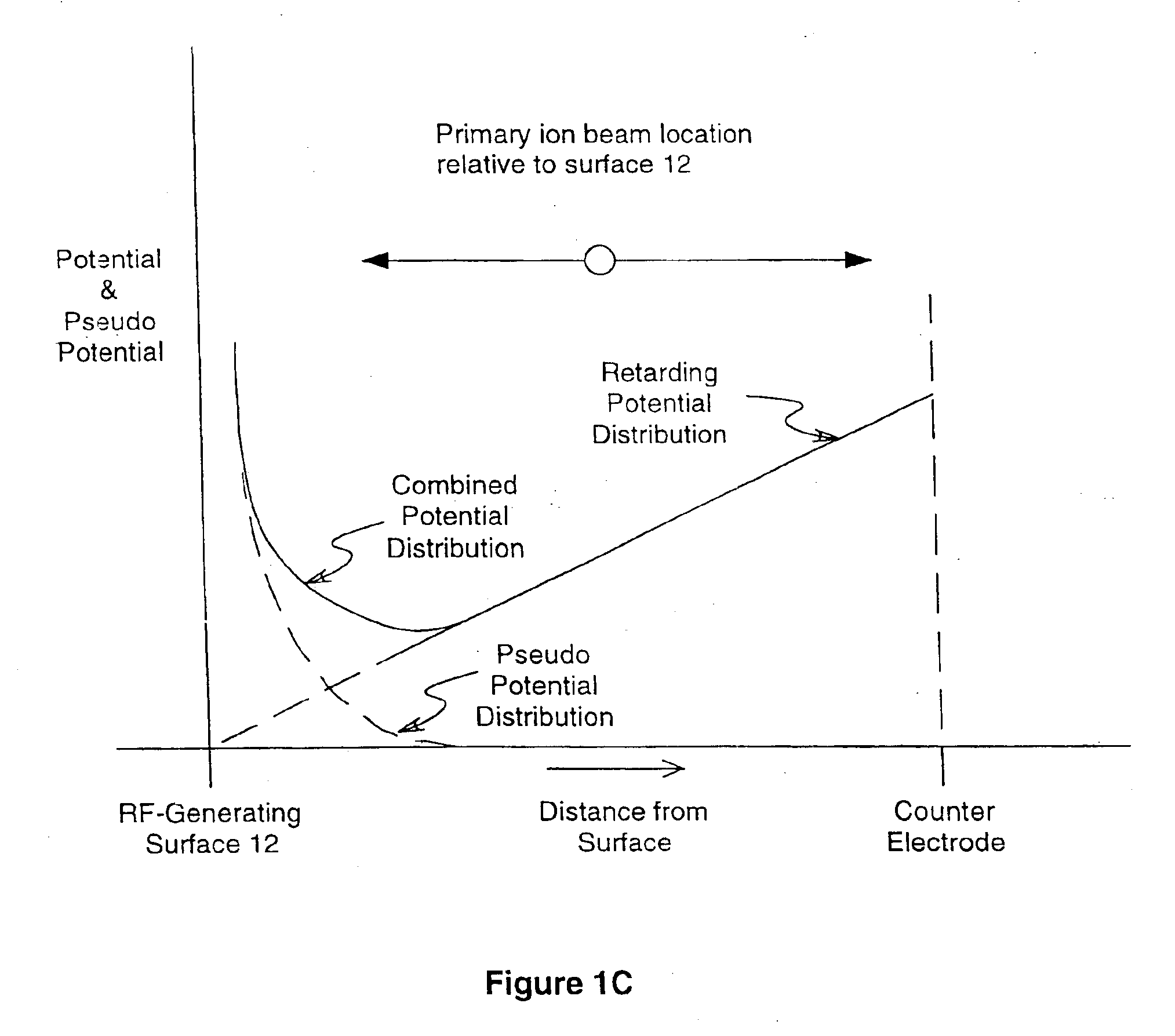
In another embodiment of the invention, the pulsing region of a Time-Of-Flight mass analyzer is comprised of two planar electrodes positioned substantially parallel and set a distance apart so as to create a gap between them. This gap is referred to as the TOF first accelerating or pulsing region. The first electrode positioned furthest from the Time-Of-Flight drift region, that is, the “pusher” electrode, is configured as an array of independent electrodes to which high-frequency potentials can be applied so as to create a pseudo potential well near the surface. The second electrode positioned nearest the TOF drift region is commonly referred to as the “counter” electrode. In conjunction with a static electric field created by static potentials applied simultaneously to these two electrodes, as well as possibly other electrodes bordering the TOF first acceleration region, a pseudo potential well is formed near the pusher electrode, to which ions are directed prior to pulsing into the Time-Of-Flight drift region. A neutral, collecting or extraction electric field can be applied between the two pulsing region electrodes to allow collecting of ions in the pseudo potential well near the pusher electrode surface, and to allow the dissipation of kinetic energy by collisions with the pusher plate surface or with
inert gas, prior to pulsing the spatially compressed ions into the Time-Of-Flight tube drift region. Alternatively, a
laser pulse can be applied to the pusher plate surface to release ions rapidly into an accelerating or delayed extraction field. In this embodiment of the invention, ions generated external to the TOF pulsing region enter the pulsing region in a direction substantially not parallel to the
planar electrode surfaces which bound the pulsing region. During the
collection period, a reverse electric field is applied across the pulsing region gap to direct ions to the potential well near the pusher electrode surface. The ions may enter the pulsing region gap with an initial trajectory that is directed either toward or away from the pusher electrode surface. After the ion
collection period, which may also include SID by high-energy collisions with the pusher electrode surface, or kinetic energy dissipation by low-energy collisions with the pusher electrode surface, or with
inert gas, the electric field is reversed in the pulsing region and ions in the pseudo potential well near the pusher surface are accelerated into the Time-Of-Flight tube for mass to charge analysis. This embodiment of the invention provides a means for directing ions into a Time-Of-Flight pulsing region from a wide variety of ion sources or
hybrid instrument electrode geometries with minimal
impact on the Time-Of-Flight performance. Depending on the electric
field strength applied to direct ions to the pseudo potential well, ions can impact the collecting surface with a low
impact energy in order to dissipate ion kinetic energy and avoid surface induced dissociation fragmentation, or with sufficient energy to cause surface induced dissociation fragmentation. Ions can be collected for a period of time prior to pulsing into the Time-Of-Flight drift region, improving the
duty cycle for some applications and operating
modes.
A variation of this scheme is to configure the rear electrode of the
reflectron, or other similar electrostatic mirror structure, not as a
solid surface which supports an RF-field generating electrode structure, but rather as a highly-transparent grid consisting of an array of fine, closely-spaced parallel wires arranged in the plane at the position that otherwise corresponds to that of the rear electrode of the
reflectron. In this grid structure, every other wire is connected together, and connected to one phase of an RF
voltage, and the remaining wires are connected together and connected to the opposite phase of the RF
voltage. Such a structure generates a highly inhomogeneous
RF field close to the plane of the wires and so forms a pseudo potential barrier near the plane of the wires for ions of moderate energy within a wide mass range. Ions of a particular mass-to-charge value can be trapped by applying a repelling potential to an intermediate grid located in front of the rear RF-field generating grid structure at the
proper time, as described above for a
solid rear
reflectron electrode. After isolating and
trapping ions of a particular mass-to-charge value, the trapped ions can be fragmented by various means, such as by interactions with photons, electrons, or ions, any of which can be directed through the
trapping region, or by allowing the trapped ions to collide with surfaces provided, for example, at the periphery of the
trapping region, or by other means. The momenta of the trapped ions and / or ion fragments can also be reduced by allowing them to collide with nearby surfaces, or with gas molecules introduced for this purpose. Trapped ions and / or ion fragments, can then be pulse accelerated along the TOF axis through the RF-field generating wire structure, in the initial TOF direction, by greatly increasing the
DC potential gradient between the intermediate trapping grid and the RF-field generating wire structure, either with or without first removing the RF-field. The ions are pulse accelerated into a subsequent TOF drift space beyond the first TOF drift space and are thereby mass-to-charge separated. This second TOF mass-to-charge analysis can also incorporate additional time-of-flight focusing devices, such as additional reflectrons, beam blanking devices, etc., in order to improve TOF performance.


