High-impact, energy-absorbing vehicle barrier system

a vehicle barrier and high-impact technology, applied in roadway safety arrangements, roads, construction, etc., can solve the problems of high-impact energy, strike the retaining wall, driver injuries and fatalities, etc., to reduce the potentially harmful deceleration force, reduce or eliminate the potential for vehicle pocketing, gouging, or snagging, and improve safety. the effect of safety

Inactive Publication Date: 2005-08-09
BOARD OF RGT UNIV OF NEBRASKA
View PDF46 Cites 55 Cited by
  • Summary
  • Abstract
  • Description
  • Claims
  • Application Information

AI Technical Summary

Benefits of technology

[0011]Another object of the present of the invention is to provide an energy-absorbing vehicle barrier system that reduces the potentially harmful deceleration forces experienced by an impacting vehicle and its occupants.
[0012]It is a further object of the present invention to provide an energy-absorbing vehicle barrier system that reduces or eliminates the potential for vehicle pocketing, gouging, or snagging in either direction of travel.
[0013]Yet another object of the present invention is to provide an energy-absorbing vehicle barrier system comprised of readily-available materials and that may be relatively easily and quickly repaired following a damaging vehicle impact.
[0014]The present invention provides for a high-impact, energy-absorbing vehicle barrier system. The barrier system generally includes a substantially rigid outer containment wall coupled via cable restraint assemblies with an energy-absorbing inner impact wall, and energy-absorbing cartridges strategically positioned between the impact wall and containment wall. A preferred embodiment of the barrier system of the present invention includes an impact wall comprised of a plurality of rectangular cross-sectioned structural steel tubes welded to one another to present a substantially smooth, uniform wall to passing vehicles. The impact wall generally consists of a number of impact wall sections coupled with one another by sliding splice units having beveled end faces. The face of the impact wall may be coated with a lubricant, such as zinc-rich paint, to further minimize friction between the impact wall and an errant, impacting vehicle. The energy-absorbing cartridges, which in a preferred embodiment consist of a plurality of foam sheets, compress and crush between the containment wall and impact wall and absorb energy from a vehicle striking the face of the impact wall. The deflection and deformation of the impact wall tubes toward the containment wall further dissipates energy of the impacting vehicle. The barrier system of the present invention is suitable for use on high-speed race tracks and public roadways, significantly reduces peak vehicular decelerations experienced by an impacting vehicle and its occupants, minimizes the potential for vehicle gouging, snagging, or pocketing in either direction of travel, and mitigates the severity of high-energy vehicular impacts. The cable restraint assemblies and sliding splice units provide for relatively easy and quick removal and replacement of damaged impact wall sections.
[0015]The new, high-impact, energy-absorbing barrier system of the present invention was developed to mitigate the severity of high-energy vehicular impacts. In impacts with rigid walls, vehicular decelerations are often maximized as the rigid wall does not displace and substantially all of the impact energy must be dissipated by the vehicle structure (e.g. the vehicle body, engine, transmission, tires, etc.). The new barrier system of the present invention reduces the severity of an impact when a vehicle strikes a containment wall at a high speed. The system reduces or eliminates snagging or pocketing in both directions of vehicle travel and also provides energy dissipation in both the impacting vehicle and the energy-absorbing barrier, significantly reducing peak vehicular and vehicle occupant decelerations when compared to the decelerations observed during an impact with a rigid containment wall. The mitigation of these high vehicular decelerations greatly reduces the potential for serious injury or fatality as a result of the impact with the exterior containment wall.

Problems solved by technology

Unfortunately, race vehicles frequently lose control and impact the rigid outer containment wall, resulting in high-impact energies and, occasionally, driver injuries and fatalities.
An impacting vehicle, however, can penetrate these foam blocks and strike the retaining wall with little or no impact energy having been absorbed by the blocks.
Further, portions of the foam blocks can be knocked onto the track or roadway by the impacting vehicle, creating a hazard for other vehicles that follow.
Although these tire barriers offer significant impact attenuation, these systems capture virtually all impacting vehicles, significantly increasing the total velocity change during the crash and greatly increasing the risk of driver injury or fatality.
Further, tire barriers can allow vehicles to under-ride the barrier and lead to intrusion into the vehicle's occupant compartment.
The PEDS barrier, however, sustained significant damage, and debris was spread across the racing surface.
This testing and simulation indicated that HDPE barrier systems allowed impacting vehicles to gouge into the material and create snagging and pocketing, indicating to the MwRSF researchers that HDPE barrier faces offered no improvements or advantages over concrete barriers.
However, the relatively short “fish scale” fender panels and the soft energy absorbers utilized in this barrier caused the system to deform around the front of the impacting vehicle, increasing the potential for snagging and / or high rebound angles at increased impact speeds.
Further, the cables and struts used to mount the barrier to the backup structure also posed potential snagging problems during high-speed impacts.

Method used


Image

  • High-impact, energy-absorbing vehicle barrier system
  • High-impact, energy-absorbing vehicle barrier system
  • High-impact, energy-absorbing vehicle barrier system

Examples


Embodiment Construction

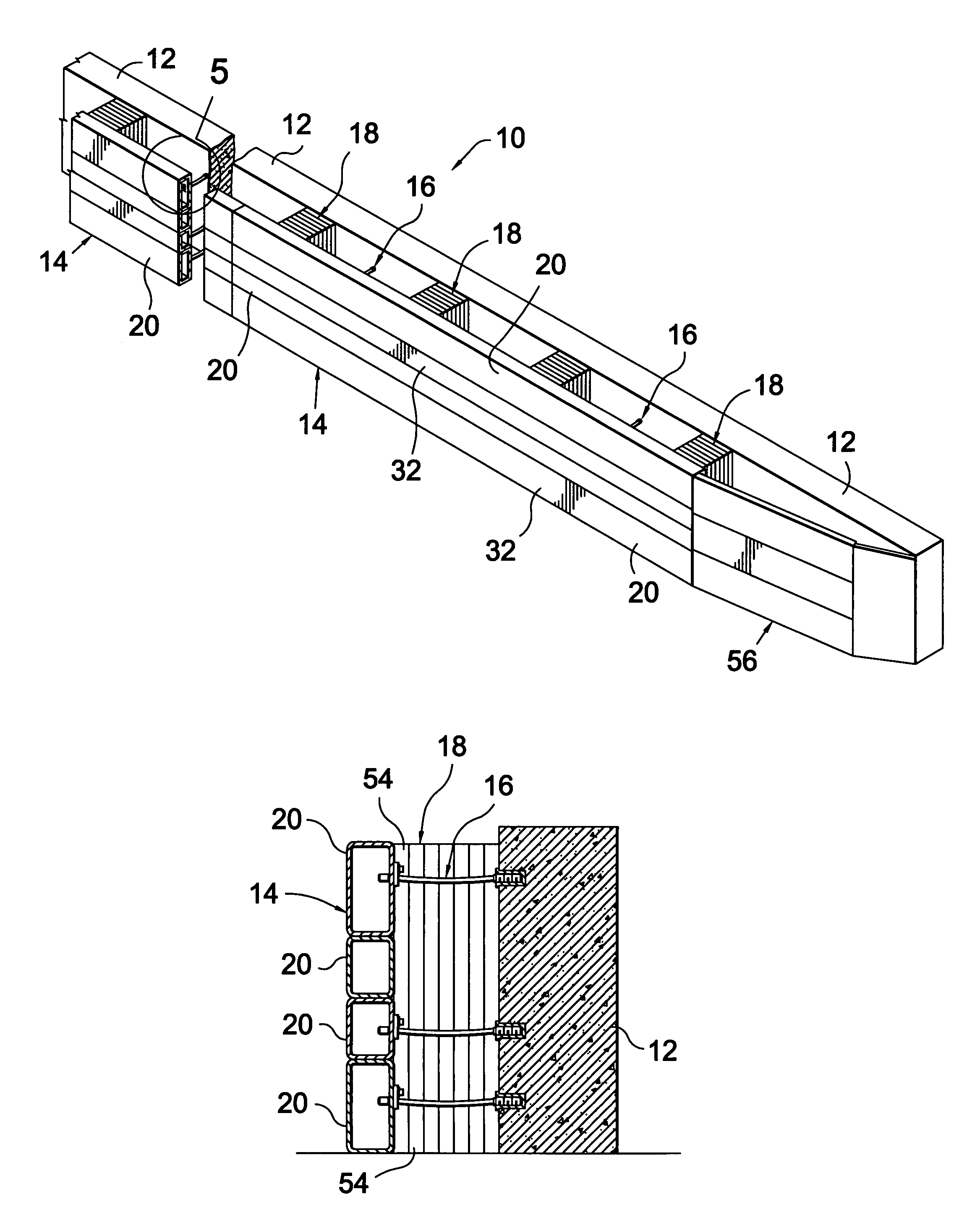
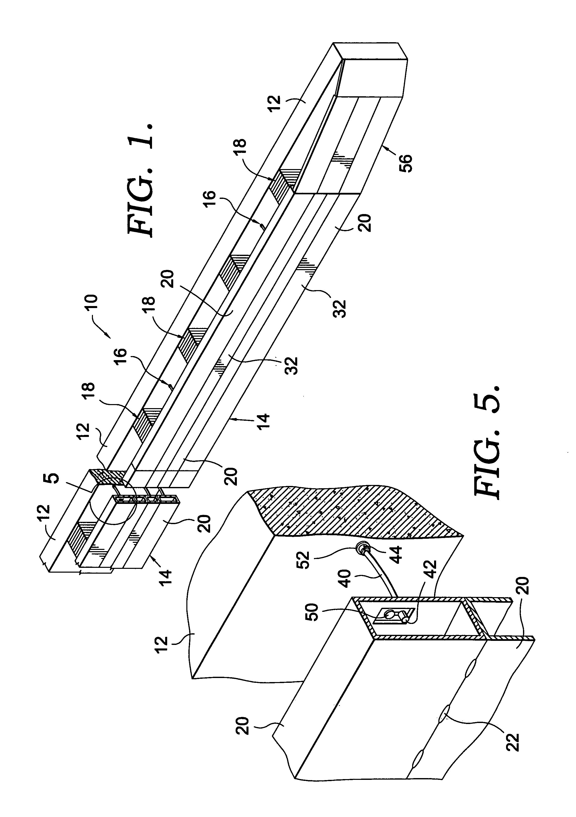
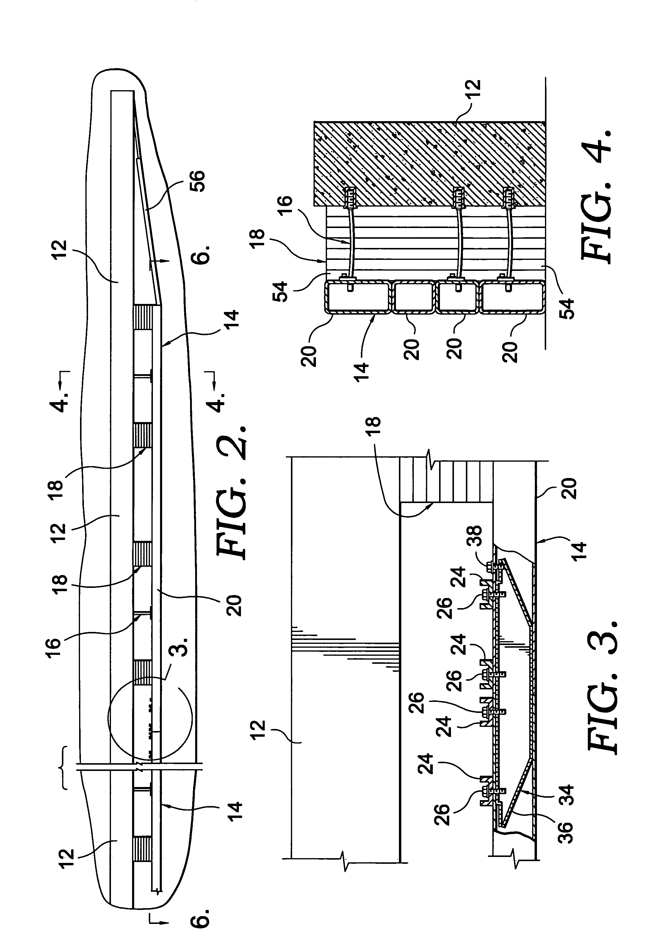
[0025]Referring to the drawings in greater detail, and initially to FIG. 1, a high-impact, energy-absorbing vehicle barrier system of the present invention is designated by the numeral 10. The barrier system 10 generally includes a substantially rigid containment wall 12, an energy-absorbing impact wall 14, a number of cable restraint assemblies 16 coupling the containment wall 12 with the impact wall 14, and a number of energy-absorbing cartridges 18 positioned between the containment wall 12 and the impact wall 14. It will be understood that the walls 12 and 14 of the barrier system 10 may be relatively straight (as depicted in FIG. 1) for use adjacent race track straightaways, for example, and / or the walls 12 and 14 may be curved for barrier system 10 installations adjacent to race track or roadway turns having a radius.

[0026]The containment wall 12 is generally constructed of heavily reinforced concrete, but may be constructed of steel, stone, or other substantially rigid materi...


PUM


Abstract

A high-impact, energy-absorbing vehicle barrier system generally includes a substantially rigid outer containment wall coupled via cable restraint assemblies with an energy-absorbing inner impact wall, and energy-absorbing cartridges strategically positioned between the impact wall and containment wall. The impact wall is constructed of a number of rectangular tubes coupled with one another to presents a substantially smooth, uniform surface to passing vehicles. The energy-absorbing cartridges generally consist of a number of foam sheets which compress and crush between the containment wall and impact wall to absorb energy from an errant vehicle striking the face of the impact wall, while the deflection and deformation of the impact wall tubes dissipates additional energy to reduce peak decelerations and mitigate the severity of high-energy vehicular impacts. The splice units and quick-disconnect cable restraint system provide for relatively easy and quick replacement of damaged impact wall sections and energy-absorbing cartridges.

Description

STATEMENT REGARDING FEDERALLY SPONSORED RESEARCH OR DEVELOPMENT[0001]Not applicable.CROSS-REFERENCE WITH RELATED APPLICATIONS[0002]Not applicable.BACKGROUND OF THE INVENTION[0003]In recent years, automobile racing has become one of the most popular sporting events in the United States and abroad. Auto racing's popularity is evidenced by the number of weekend auto races, extensive fan support and corporate sponsorship, and 24-hour cable television coverage. In addition, the sport's popularity is seen in the wide variety of race series available for drivers and spectators, including the Indy Racing League (IRL), NASCAR's WINSTON CUP, BUSCH, and Truck series, FORMULA 1, CART, and IROC.[0004]In automobile racing, high-performance vehicles travel many times around an oval track at very high speeds. Many of these tracks utilize outer retaining or containment walls, typically in the form of substantially rigid concrete barriers, to prevent race vehicles from leaving the track. Unfortunatel...

Claims


Application Information

Patent Timeline
Patent Type & Authority Patents(United States)
IPC IPC(8): E01F15/00E01F15/14
CPCE01F15/083E01F15/086
Inventor FALLER, RONALD K.SICKING, DEAN L.ROHDE, JOHN R.REID, JOHN D.KELLER, ERIC A.BIELENBERG, ROBERT W.HOLLOWAY, JAMES C.ADDINK, KENNETH H.POLIVKA, KARLA A.
Owner BOARD OF RGT UNIV OF NEBRASKA
Why Eureka
Try Eureka