Hand dryer

a dryer and hand technology, applied in the field of hand dryers, can solve the problems of increasing energy consumption, requiring more energy and time, and evaporative drying requires this additional time, so as to reduce air impact noise, less noise, and dissipate impact energy

Inactive Publication Date: 2009-05-14
INVENT RESOURCES
View PDF0 Cites 52 Cited by
  • Summary
  • Abstract
  • Description
  • Claims
  • Application Information

AI Technical Summary

Benefits of technology

[0043]This invention achieves significant reduction in air impact noise by presenting the blow-off air to the hands by using an array of long smaller nozzles (sub-nozzles) situated within a sin

Problems solved by technology

Evaporative drying changes the physical state of the water to be dried away from liquid to vapor and thus requires more energy and more time than blow-off drying which merely moves the water off the hands.
Blow-off drying alone always leaves a small amount of moisture on the hands that result in discomfort due to evaporative cooling of the hands.
Evaporative drying requires this additional time because the air stream is diffuse and dissipates much of its energy in heating surrounding air rather than the hands.
The longer time that the hand dryers need to operate and dry, the more electrical power is used, and this can be a serious problem because of the cost, increasing cost, and limited availability of energy.
In fact, sometimes users of conventional dryers find they must repeat the drying cycle in order to dry the hands more completely, which increases the energy usage.
In addition, because of the longer drying time otherwise needed, users are sometimes reluctant to wash their hands when using public washrooms, and this can encourage the transmission of infections.
This can be potentially serious if problems such as bird flu mutate to the point where they become infectious and transmissible among humans.
This enclosure is awkward for the user, with the risk of contacting the nearby enclosure walls and infectious material.
Dryer nozzles present a problem in that users are often tempted to stuff napkins or towels into them, hoping to cause a pressure driven “explosion”.
The longer drying time of other hand dryers can result in longer discouraging waiting time in public bathrooms where there are many people waiting their turn to use the slower dryer.
This can reduce the number of people who would otherwise wash their hands, thus resulting in reduced hygiene and safety.
Conventional dryers suffer from low energy eff

Method used


Image

  • Hand dryer
  • Hand dryer
  • Hand dryer

Examples


embodiment

Preferred Embodiment

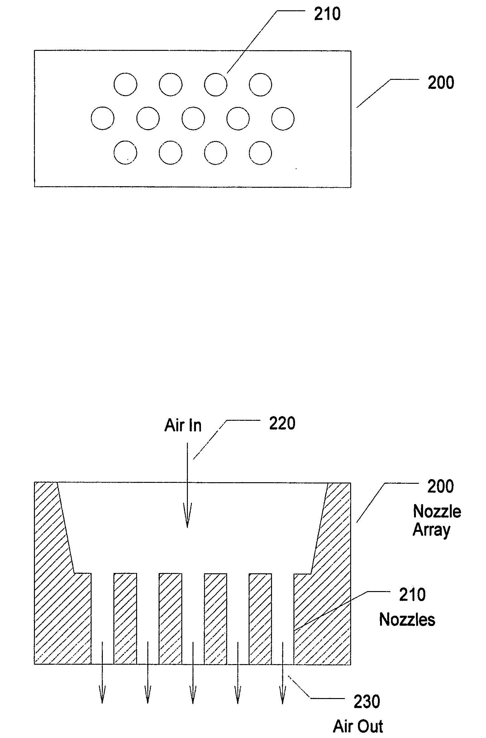
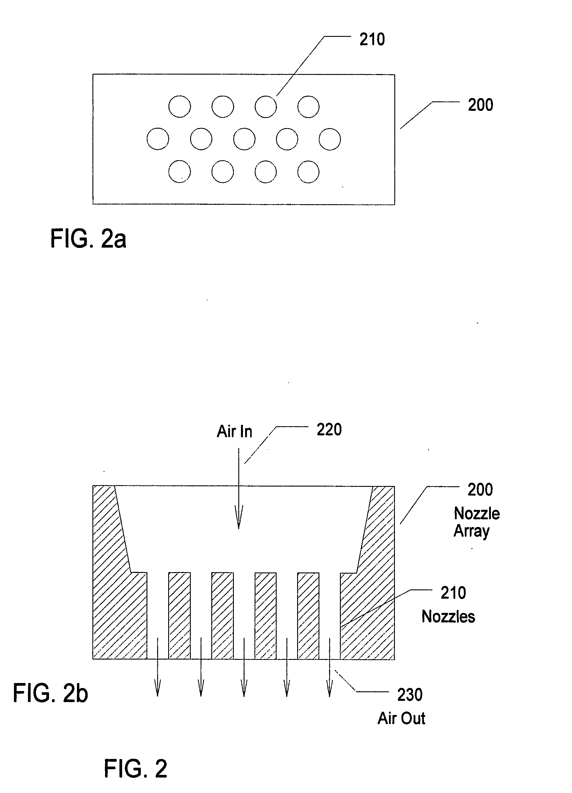
[0081]A preferred version of our dryer has a compound directional nozzle containing multiple cylindrical air exit sub-nozzles with spacing between the cylindrical sub-nozzles. This reduces the measured hand impact noise produced by the turbulence of the individual air streams on the hands. For the case of spacing between the fast air streams there is a shorter path for the high velocity air at the impact location to escape to a region with less airflow, and less turbulence. For dryers that use fast streams of air for drying, the noise produced when the fast flowing air impacts the surface to be dried, can be high enough to disturb the user or even others in adjacent locations. In one version of our dryer, the compound directional nozzle consisting of multiple, parallel tubular exit sub-nozzles are used to result in reduced noise that would be produced when a fast air jet impacts on surfaces.

[0082]The multi-jet design allows for tilting jets to different angles of...


PUM


Abstract

A dryer uses a high-speed blower producing high velocity air, a heater and a compound directional nozzle containing multiple tubular, cylindrical air sub-outlets to generate both suitable force and temperature in the sub-jets of air to dry the user's hands. The air outlets are sized and shaped to maintain direction of airflow at the location of the hands. The multiple tubular sub-nozzles reduce the air turbulence noise from the fast airflow sub-jets striking the hands by providing spaces between the adjacent sub-nozzles and air sub-jets so that the turbulence and hand impact noise is reduced and so that the water evaporated from the water film has a shorter escape distance. An ion source provides ions in the output air from the compound directional nozzle to enhance evaporation.

Description

BACKGROUND OF THE INVENTION[0001]1. Field of the Invention[0002]The present invention relates to lowering air impact noise of the air used in drying hands and the like with a blower-type dryer, and is achieved by using a compound directional nozzle containing an array of sub-nozzles.[0003]2. Description of the Related Art[0004]Conventional hand dryers dry an individual's wet hands in one of two ways, evaporative drying or “blow-off” drying. (In the blow-off case, a small amount of evaporation occurs, but it is incidental and minimal since the air stream usually is not yet warmed at the start because of the thermal time lag.)[0005]Conventional evaporative hand dryers include a blower for generating an air stream through a ducting system to one or more air exit outlets that directs the air stream onto the hands of the user. An internal heating device may be included to heat the air stream. The hand dryers generally include a push button, photocell sensor or other means to actuate the ...

Claims


Application Information

Patent Timeline
IPC IPC(8): F26B21/00F26B7/00
CPCA47K10/48
Inventor AISENBERG, SOLFREEDMAN, GEORGEPAVELLE, RICHARDHED, AHARON ZEEV
Owner INVENT RESOURCES
Why Eureka
Try Eureka