Waveform plate web girder

A corrugated web, plate beam technology, applied in joists, girders, truss beams, etc., can solve the problems of shear buckling strength and shear bearing capacity to be improved, achieve good designability and practicability, and improve bearing capacity. Powerful, lightweight effect

Inactive Publication Date: 2009-03-04
万水
View PDF0 Cites 23 Cited by
  • Summary
  • Abstract
  • Description
  • Claims
  • Application Information

AI Technical Summary

Problems solved by technology

[0002] The existing beam structure is usually an I-beam, which is composed of a vertical web and two parallel flange plates. The commonly used web is a flat web, but its shear buckling strength and shear bearing capacity are both low. needs improvement

Method used


Image

  • Waveform plate web girder
  • Waveform plate web girder
  • Waveform plate web girder

Examples


Embodiment 1

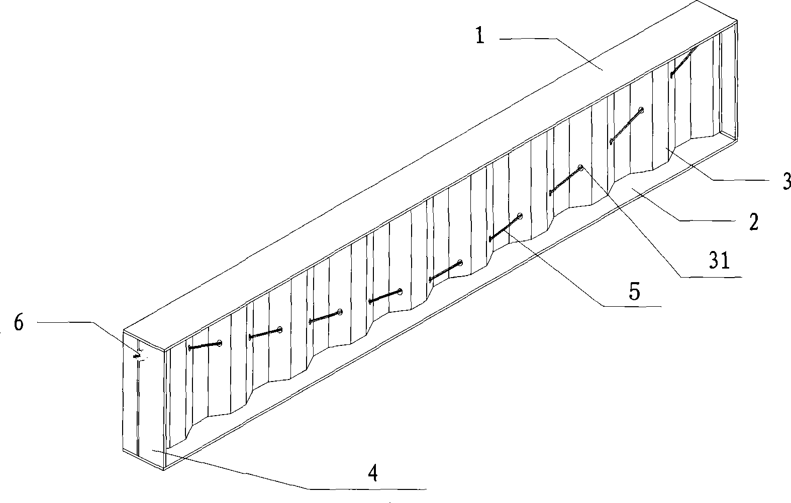
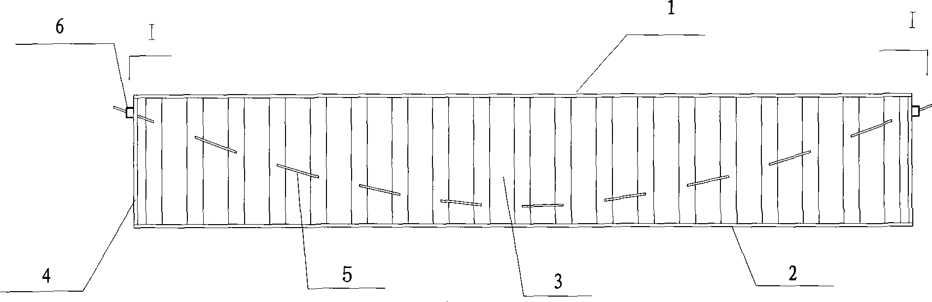
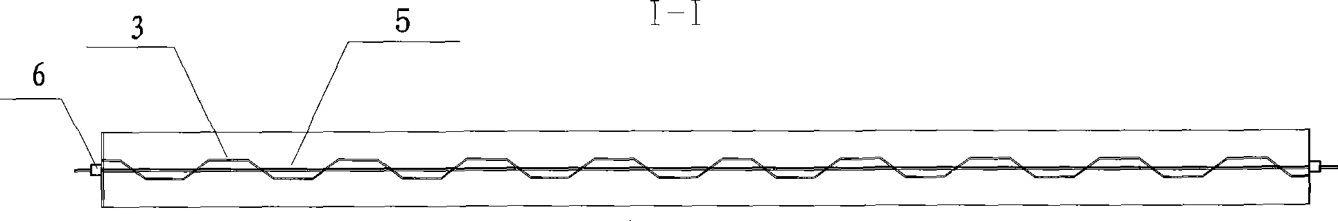
[0023] Such as Figure 1-3 , a corrugated web beam, consisting of an upper flange plate 1, a lower flange plate 2, a corrugated web plate 3, a hole 31 on the corrugated web plate, a beam end plate 4, a prestressed tendon 5 and an anchor 6; the beam The end plates 4 are located at both ends of the beam, and are connected with the upper flange plate 1, the lower flange plate 2 and the corrugated plate 3, and the holes 31 are located in the obliquely folded plate part of the corrugated web 3, relative to a prestressing tendon 5 The holes are lowered sequentially from both ends to the middle, and the prestressed tendons 5 pass through the holes 31 on the corrugated web 3, and after being stretched, they are fixed on the end plates 4 at both ends of the beam by the anchors 6, forming a line shape with upward notches . The corrugated web 3 is made of metal material, and the prestressing rib 5 is made of metal or carbon fiber material.

Embodiment 2

[0025] It is basically the same as Embodiment 1, except that there are two prestressed tendons with upward notches on the corrugated web. The prestressing tendons are made of carbon fiber material; the corrugated web is made of resin-based fiber-reinforced plastic.

Embodiment 3

[0027] refer to Figure 4-6 , a corrugated web beam, consisting of an upper flange plate 1, a lower flange plate 2, a corrugated web plate 3, a beam end plate 4, a stiffened rib plate 7, a hole 71 on the stiffened rib plate, and prestressed ribs 5 Composed of an anchor 6, a plurality of stiffened ribs 7 are arranged symmetrically on both sides of the corrugated web 3, and the stiffened plates 7 are connected with the upper flange plate 1, the lower flange plate 2 and the corrugated web 3. The prestressed tendons 5 pass through the holes 71 on the stiffened plates 7 on both sides of the corrugated web 3 to form a line with notches upward, and are fixed on the beam end plates 4 at both ends of the beam by anchors 6 after being stretched. The corrugated web 3 is made of metal material, and the prestressing rib 5 is made of metal material or carbon fiber material.


PUM


Abstract

The present invention relates to a corrugated plate web girder. The structure of the corrugated plate web girder comprises an upper flange plate, a lower flange plate and a corrugated web. The corrugated plate web girder has the following characteristics: prestressed ribs, which are fixed on girder end plates by anchors, are arranged on the corrugated web; or reinforced rib plates with holes are arranged on both sides of the corrugated web; and the prestressed ribs pass through the reinforced rib plates and are fixed on the reinforced rib plates of both ends by the anchors. The corrugated plate web girder has the following advantages: the corrugated plate web girder adopts the prestressing technology, so the bearing capability of the girder structure is enhanced; the weight is light, so the corrugated plate web girder can be adapted to a large span; and the corrugated plate web girder has good designability and practicability.

Description

technical field [0001] The invention belongs to the field of beam structures, in particular to a prestressed corrugated web beam structure. Background technique [0002] The existing beam structure is usually an I-beam, which is composed of a vertical web and two parallel flange plates. The commonly used web is a flat web, but its shear buckling strength and shear bearing capacity are both low. needs improvement. Corrugated web beams have the advantage of high shear buckling strength, and the use of thinner corrugated plates can enable the beam to obtain a higher shear bearing capacity, thereby effectively improving the bearing capacity of the beam structure and reducing the weight of the equipment. Contents of the invention [0003] The technical problem to be solved by the present invention is to provide a corrugated web girder, which adopts prestressing technology to improve the bearing capacity of the corrugated web girder. [0004] One of the technical schemes for s...

Claims


Application Information

Patent Timeline
Patent Type & Authority Applications(China)
IPC IPC(8): E04C3/02E04C3/10E04C3/28
Inventor 万水朱坤宁李淑琴谢发祥陈建兵
Owner 万水
Why Eureka
Try Eureka