Circuit breaker

A circuit breaker and circuit technology, applied in the direction of circuits, circuit breaker parts, circuit breaker contacts, etc., can solve the problem of not being able to exert the breaking performance of two-point breaking circuit breakers, and achieve the effect of high insulation strength

Active Publication Date: 2009-03-04
FUJI ELECTRIC FA COMPONENTS & SYST CO LTD
View PDF2 Cites 16 Cited by
  • Summary
  • Abstract
  • Description
  • Claims
  • Application Information

AI Technical Summary

Problems solved by technology

Therefore, when the arc voltage of the arc elongated between the fixed/movable contacts becomes more than the dielectric strength between the fixed contacts 1 and 2 arranged left and right, the insulation between the fixed contacts is broken, causi

Method used


Image

  • Circuit breaker
  • Circuit breaker
  • Circuit breaker

Examples


Embodiment Construction

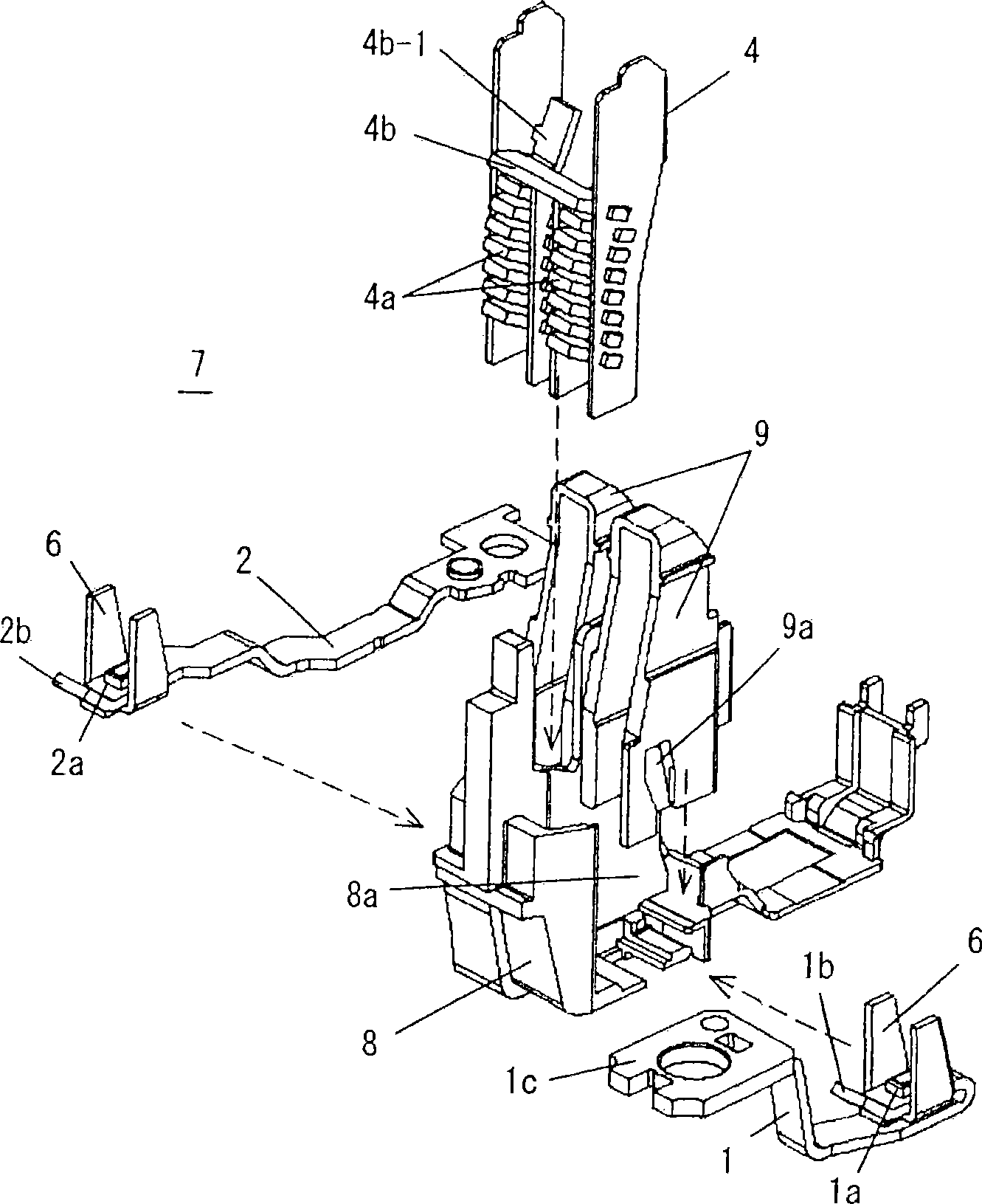
[0044] The following is based on Figure 1 to Figure 6 The examples shown illustrate embodiments of the invention. In the following embodiments, although various limitations are made on constituent elements, types, combinations, shapes, relative arrangements, etc., these are merely examples, and the present invention is not limited thereto.

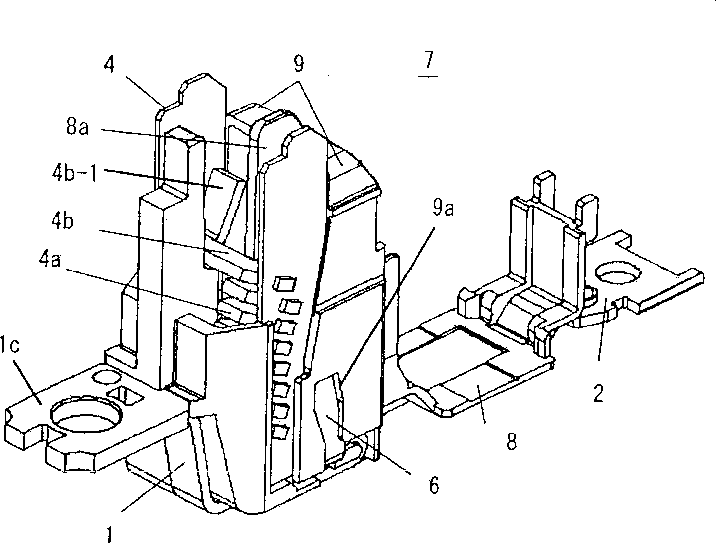
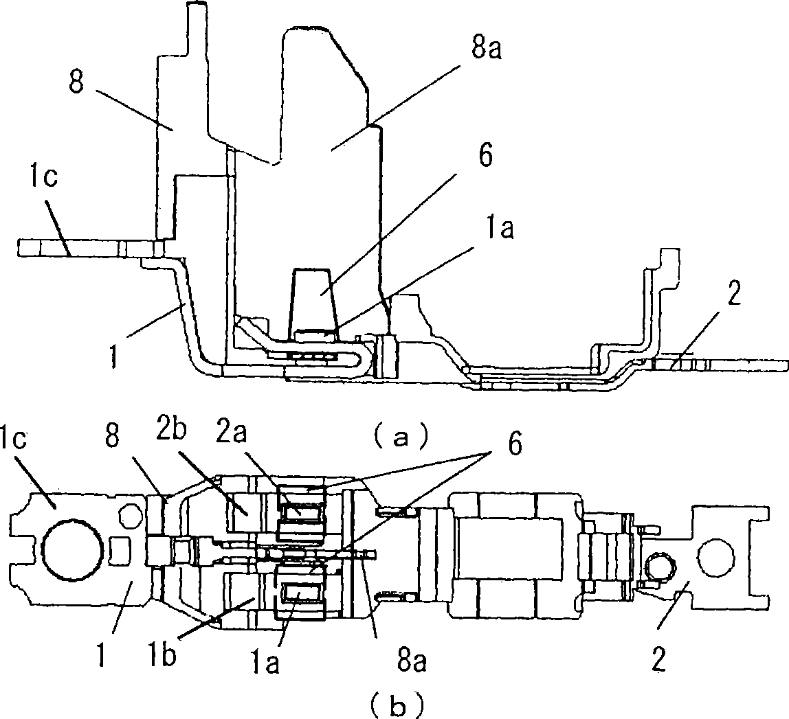
[0045] figure 1 It is an exploded perspective view showing the unit assembly structure of the current breaking unit, figure 2 is the external view of the assembled state of the unit, image 3 (a) and (b) indicate that the components of the fixed contact and the yoke are assembled on the figure 1 The side view and plan view of the state in the unit assembly frame of , Figure 4 (a) to (d) are side views, plan views, end views and X-X cross-sectional views showing the state of assembling the arc extinguishing device, the yoke, and the yoke cover in the unit assembly frame, Figure 5 It is a perspective view showing the arrangement o...


PUM


Abstract

The present invention relates to a circuit breaker. The circuit breaker is composed of a right and left parallel configured first and second fixed contact, rotary type bridging type movable contacts providing movable connection points on a U-shaped arm, and gate arc-control devices respectively corresponding configured with the first and second fixed contacts. In a two-point disconnecting mode circuit-breaking switch loading these components in a unit assembling frame body, a U-shaped magnet yoke surrounding a connection point section of fixed contacts from right and left, and the side edge section of the U-shaped magnet yoke can stand along the broken circuit moving path of the movable contacts; an insulating barrier and a yoke cover made from insulation materials are provided in the unit assembling frame body, the insulating barrier is inserted between fixed contacts and extends along the broken circuit moving path of the movable contacts; the yoke covers are provided on the right and left sides of the insulating barrier, covers the right and left side edge sections of the magnet yoke from inner side, and are insulated from the fixed contacts; and an electric arc converter board is provided on the upper segment of the arc-control device spanning the right and left arc-extinguishing chambers.

Description

technical field [0001] The present invention relates to a circuit breaker suitable for wiring of low-voltage power distribution lines. Two pairs of switching contacts are combined in series at the current breaking part of each pole to make the circuit breaker of the two-point breaking method for overcurrent breaking. Specifically, it relates to the cell structure of its current interrupting unit. Background technique [0002] A circuit breaker of a two-point breaking system is known in which two pairs of switching contacts are connected in series to a current breaking part of each pole to break an overcurrent (for example, refer to Patent Document 1). [0003] The current breaking unit of the two-point breaking circuit breaker is composed of first and second fixed contacts, a rotary bridging type movable contact, and an arc extinguishing device. The above-mentioned first and second fixed contacts are arranged left and right, and fixed contacts are fixed at their front ends;...

Claims


Application Information

Patent Timeline
IPC IPC(8): H01H73/18H01H9/44
CPCH01H9/34H01H71/2409H01H73/04H01H2071/249
Inventor W·P·H·德西瓦浅川浩司满重三弘三浦正夫佐藤佑高
Owner FUJI ELECTRIC FA COMPONENTS & SYST CO LTD
Why Eureka
Try Eureka