
Voltage Regulator

A voltage regulator and output voltage technology, applied in the direction of adjusting electrical variables, control/regulation systems, instruments, etc., can solve problems such as battery damage, battery explosion, and danger

Active Publication Date: 2020-07-07
NANJING SILERGY SEMICON TECH CO LTD
View PDF5 Cites 0 Cited by
  • Summary
  • Abstract
  • Description
  • Claims
  • Application Information

AI Technical Summary

Problems solved by technology

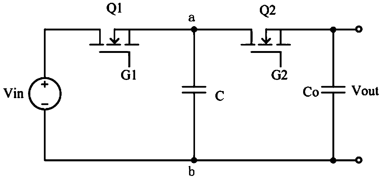
[0003] However, in the existing architecture of the switched capacitor converter, when the switch Q1 and / or the switch Q2 are damaged, such as a short circuit, the input voltage Vin and the output voltage Vout are short-circuited, and the input voltage Vin directly supplies power to the load at the output end
At this time, assuming that the load is a battery, if the input voltage Vin is high, the high voltage is directly supplied to the rechargeable battery, which may cause battery damage or even battery explosion, which is not good for electronic systems and equipment. Allowed, but also very dangerous, need to provide the necessary protective measures to avoid such situations from happening

Method used


Image

  • Voltage Regulator
  • Voltage Regulator
  • Voltage Regulator

Examples


Embodiment Construction

[0048] The present invention is described below based on examples, but the present invention is not limited to these examples only. In the following detailed description of the invention, some specific details are described in detail. The present invention can be fully understood by those skilled in the art without the description of these detailed parts. Well-known methods, procedures, procedures, components and circuits have not been described in detail in order to avoid obscuring the essence of the present invention.

[0049] Furthermore, those of ordinary skill in the art will appreciate that the drawings provided herein are for illustrative purposes and are not necessarily drawn to scale.

[0050] Meanwhile, it should be understood that in the following description, "circuit" refers to a conductive loop formed by at least one element or sub-circuit through electrical connection or electromagnetic connection. When an element or circuit is referred to as being "connected"...


PUM


Abstract

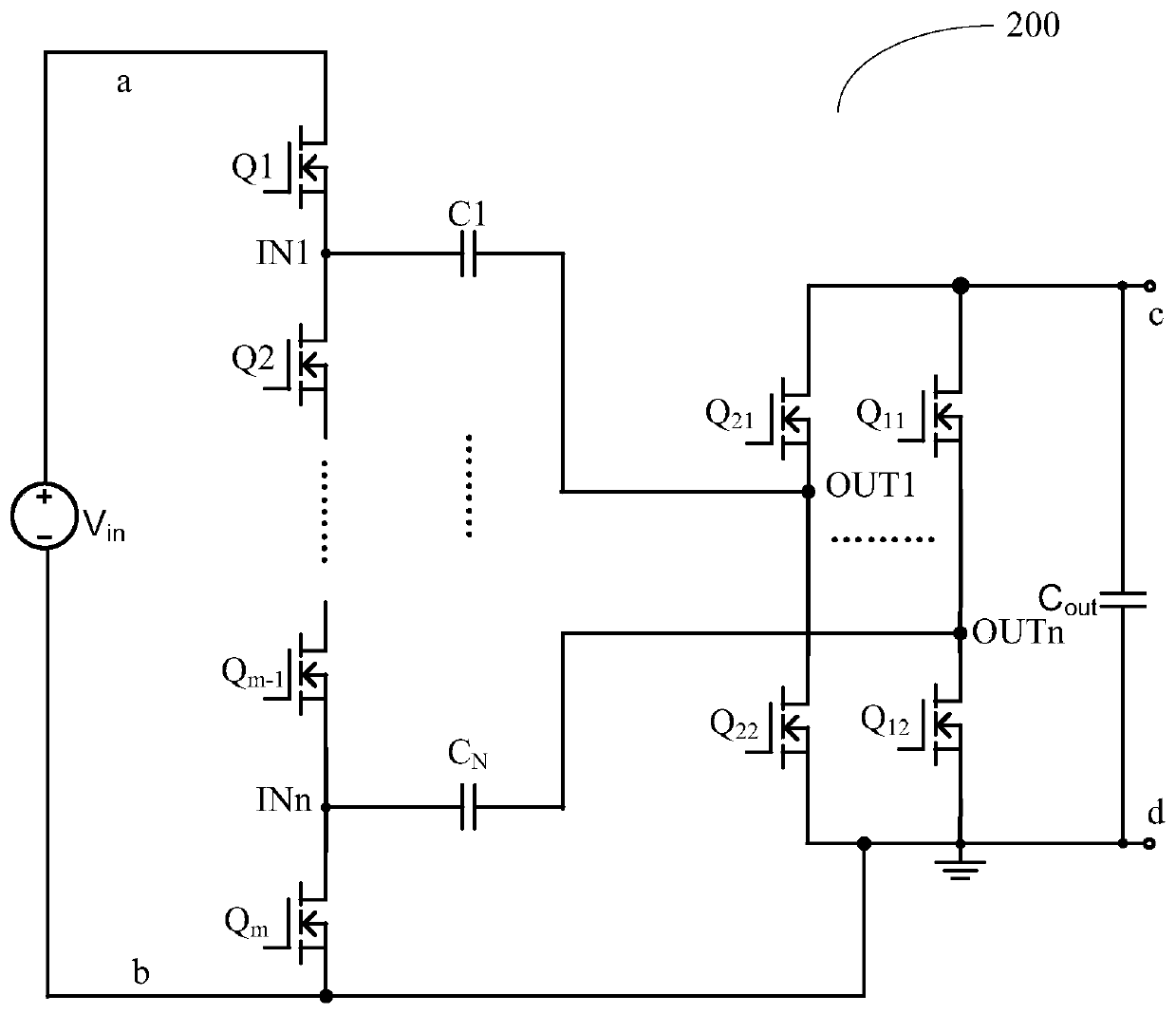
According to the embodiment of the present invention, a new voltage regulator is disclosed, the input port and the output port have a common ground potential; it includes a group of input switches connected in series between the input ports, and the common node of two adjacent input switches serves as Input switch node; at least one output half-bridge circuit connected between the output ports, each of the output half-bridge circuits includes two output switches connected in series, and the common node of the two output switches is used as the output switch node; N an energy storage capacitor; the first end of each energy storage capacitor is connected to a corresponding input switch node, and the second end is connected to an output switch node; an output switch node can be connected to the second end of a plurality of different energy storage capacitors The switching states of the input switch and the output switch are controlled and switched to control the charging and discharging state of the energy storage capacitor, so that the ratio of the input voltage to the output voltage is N, where N is a natural number not less than 1.

Description

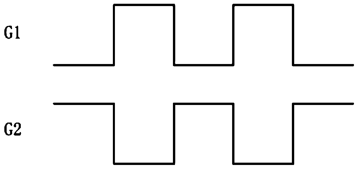
technical field [0001] The present invention relates to the technical field of power electronics, and more particularly to a voltage regulator. Background technique [0002] Switched capacitor voltage regulators control the charging and discharging of capacitors by switching to achieve voltage conversion. Existing switched capacitor voltage regulators such as Figure 1A As shown, an input voltage Vin is applied to the input port. The switch Q1 is connected between the terminal a of the capacitor C and the first terminal i of the voltage input port, and is turned on or off under the control of the control signal G1. The switch Q2 is connected between the end a of the capacitor C and the first end of the output port, and is turned on or off under the control of the control signal G2. refer to Figure 1B Shown are the working waveforms of control signals G1 and G2. The control signals G1 and G2 are inverted, that is, when the control signal G1 is at a high level, the contro...

Claims


Application Information

Patent Timeline
Patent Type & Authority Patents(China)
IPC IPC(8): G05F1/613
CPCH02M1/32H02M3/07G05F1/44G05F1/575
Inventor 张望赵晨毛浪
Owner NANJING SILERGY SEMICON TECH CO LTD
Learn More