High-power LED lens

A LED lens and high-power technology, applied in the field of LED lighting, can solve the problems of scattered light spots, concentrated light spots, uneven illumination, etc., and achieve the effects of reasonable light distribution, reduced invalid loss, and uniform illumination

Inactive Publication Date: 2009-03-11
广东佳兆业佳云科技股份有限公司
View PDF0 Cites 9 Cited by
  • Summary
  • Abstract
  • Description
  • Claims
  • Application Information

AI Technical Summary

Problems solved by technology

At present, the light spots formed on the road surface of existing LED street lights can be divided into rectangular light spots, circular light spots and elliptical light spots, among which the light distribution of rectangular light spots is the most reasonable, which reduces the ineffective loss of light; but the existing high-power LED street lights , the secondary lighting conditions are generally divided into two types, one is to use a light cup, and the other is to use a lens. There are problems such as heat dissipation of high-power LED street lamps, and the cost is increased, which cannot achieve the purpose of cost saving
The disadvantage of the latter is that the light spots are too concentrated, which is manifested in the fact that the center illuminance of the road surface light spots is very high, for example, the center illuminance reaches 35LUX, while the edge or street light poles have low illuminance or shadows, and the illuminance is only below 1LUX

Method used


Image

  • High-power LED lens
  • High-power LED lens
  • High-power LED lens

Examples


Embodiment Construction

[0031] In order to further understand the features, technical means, and specific objectives and functions achieved by the present invention, the present invention will be further described in detail below in conjunction with the accompanying drawings and specific embodiments.

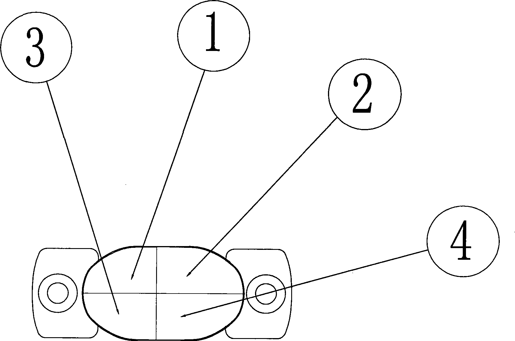
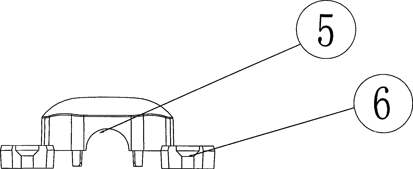
[0032] The related structure of the present invention mainly includes the following components (or devices): first parabolic aspheric surface 1, second parabolic aspheric surface 2, third parabolic aspheric surface 3, fourth parabolic aspheric surface 4, U-shaped groove 5, and mounting base 6.

[0033] Structural devices as attached figure 1 , attached figure 2 As shown, the LED lens of the present invention includes the first parabolic aspheric surface 1, the second parabolic aspheric surface 2, the third parabolic aspheric surface 3, and the fourth parabolic aspheric surface 4 of the LED lens. The light is redistributed to make the illumination of the LED spot as uniform as possible, and it is des...


PUM


Abstract

The invention provides a large power LED lens which has averaged facula uniformity, reasonable structure and convenient installation, and can meet the requirement of large power illumination of street lamps. The LED lens has the advantages of beautiful facula, uniform facula, convenient installation and the like. The LED lens comprises an installation base which is provided with a U-shaped concave trough which is concave inwards; the U-shaped concave trough is internally provided with an LED bulb; the upper surface of the U-shaped concave trough is provided with four surfaces sequentially as follows: a first parabola non-sphere, a second parabola non-sphere, a third parabola non-sphere and a fourth parabola non-sphere, wherein, the first parabola non-sphere is symmetric to the second parabola non-sphere, the third parabola non-sphere and the fourth parabola non-sphere; the LED lens is designed according to the concept of rectangular facula on the road surface, utilizes the secondary optical principle to lead the facula to be uniformly distributed on the four surfaces of the LED lens, has the advantages of uniform facula illumination on the road surface and reasonable distribution of light beam, reduces the ineffective loss of the light beam, and has low price, convenient installation and generalization significance.

Description

technical field [0001] The invention relates to an LED lighting technology. A secondary optical lens body is jointly defined by a secondary optical lens, a base surface, a light incident surface and a light exit surface, and in particular relates to a high-power LED lens. Background technique [0002] At present, the energy shortage in the world has caused countries to attach great importance to energy-saving technologies. While vigorously developing renewable and clean energy such as solar energy and wind energy, countries have also increased development efforts in the rational use of energy. Now on the road The street lamps used are all 150W ~ 400W, and the power source for lighting consumes a lot of power. Due to the large demand for general street lamps, the power supply is very large, which brings great pressure on energy consumption. Among them, light-emitting diodes, High-power LED street lamps have begun to be applied to road lighting. At present, the light spots fo...

Claims


Application Information

Patent Timeline
Patent Type & Authority Applications(China)
IPC IPC(8): F21V5/04H01L33/00F21Y101/02F21Y115/10
CPCF21Y2101/02F21W2131/103F21V5/04F21Y2115/10
Inventor 周建林
Owner 广东佳兆业佳云科技股份有限公司
Why Eureka
Try Eureka