Timepiece and portable device
A technology of clocks and hammers, which is applied in the field of clocks and portable equipment, can solve the problems of hindering the vibration of the gong and not making a good sound, so as to achieve the effects of no vibration attenuation, prolonging the duration of the clockwork, and reducing wear and tear
- Summary
- Abstract
- Description
- Claims
- Application Information
AI Technical Summary
Problems solved by technology
Method used
Image
Examples
no. 1 approach
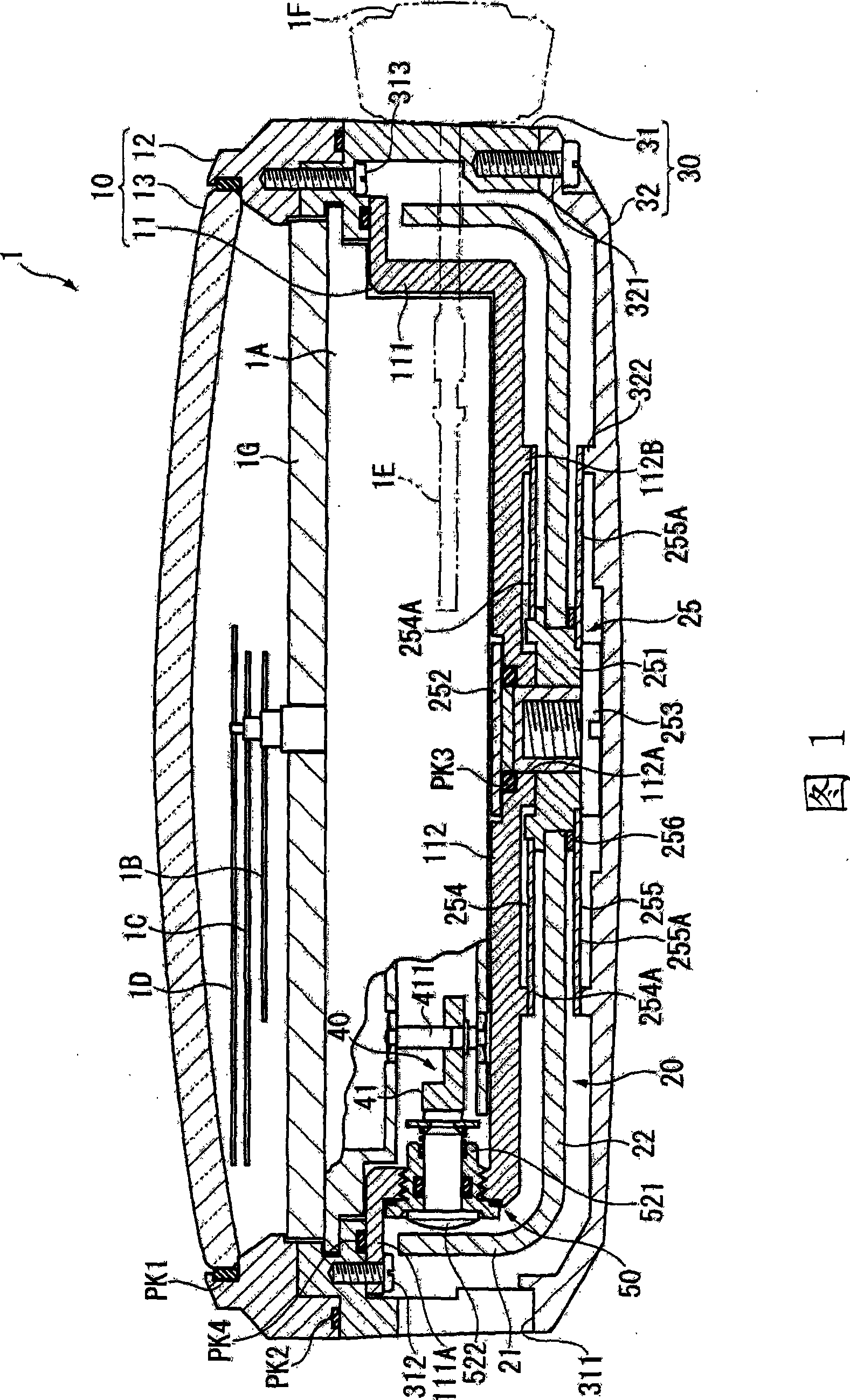
[0102] A first embodiment of the present invention will be described with reference to FIGS. 1 to 5 .
[0103] [1. Overall structure]
[0104] FIG. 1 is a longitudinal sectional view showing a timepiece 1 according to a first embodiment of the present invention. The timepiece 1 has a movement 1A as a main body, an inner case 10 housing the movement 1A, a bell 20 as a bowl-shaped sound source provided outside the inner case 10 , and an outer case 30 covering the bell 20 . The timepiece 1 of the present embodiment is an electronically controlled mechanical timepiece that drives the hands by the driving force of the mainspring, and supplies electric power generated by the driving force of the mainspring to an electronic circuit to adjust the speed.
[0105] Although not shown, the movement 1A has: a mainspring; a drive train that drives the hour hand 1B, minute hand 1C, and second hand 1D with the driving force of the mainspring; a generator that generates electricity using the ...
no. 2 approach
[0199] Next, refer to Figure 6~ Figure 8 A second embodiment of the present invention will be described.
[0200] In this embodiment, a gong is used as a sound source instead of a bell, and the timepiece of this embodiment has a repeater mechanism. In addition, the timepiece of this embodiment is a transparent cover (see through back) specification in which glass is provided on the back cover side. Furthermore, in this embodiment, a striking force transmission member different from that of the first embodiment is used. Except for these points, the timepiece of this embodiment has substantially the same configuration as the timepiece 1 of the first embodiment.
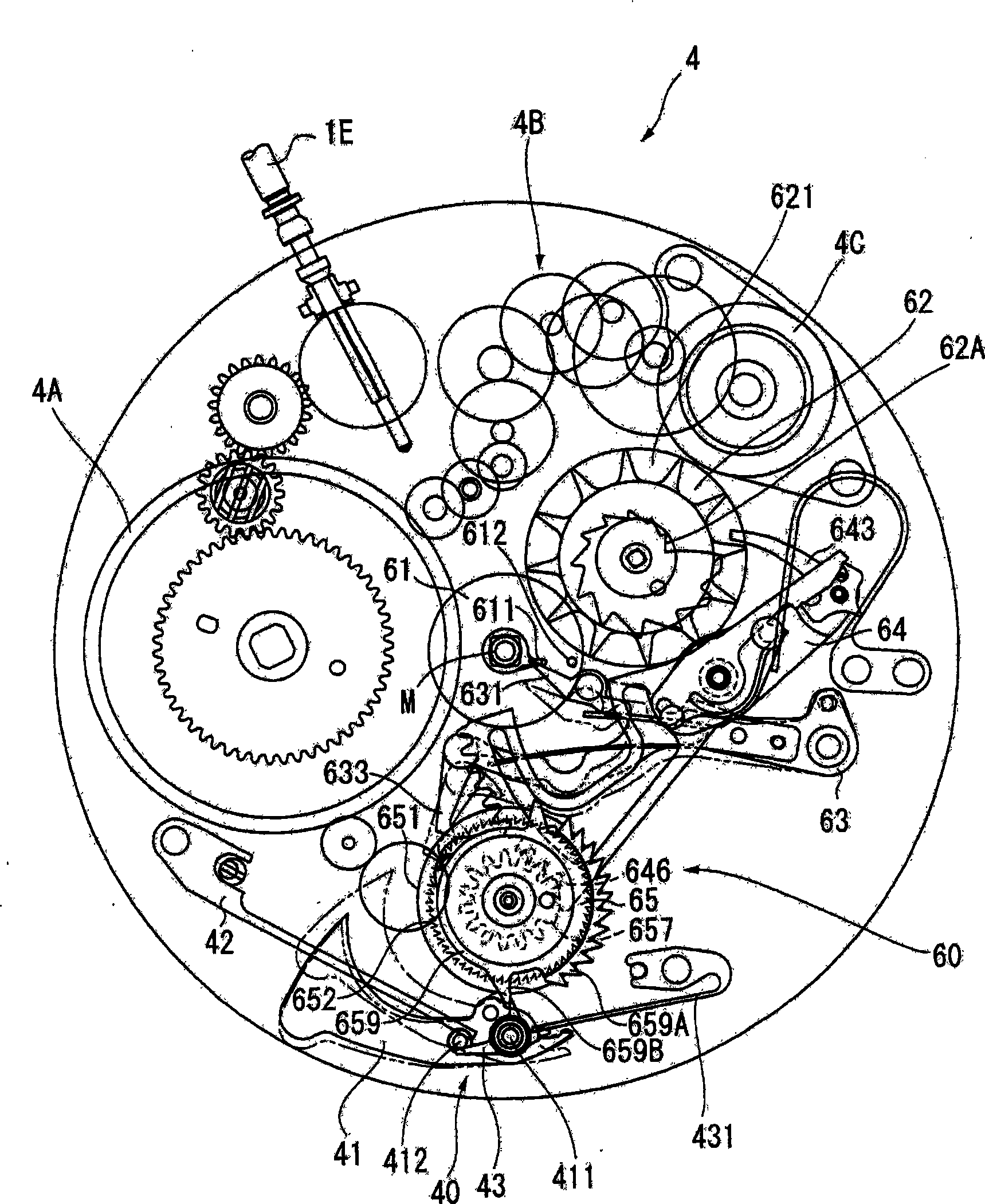
[0201] FIG. 6 is a longitudinal sectional view of the timepiece 7 according to this embodiment, and FIG. 7 is a transverse sectional view of the timepiece 7 . In addition, in FIG. 7, the components other than the hammer main body 41 and the hammer release device 43 of the movement are not shown in figure.
[0202] ...
no. 3 approach
[0233] Next, refer to Figure 9~ Figure 11 A third embodiment of the present invention will be described.
[0234] In this embodiment, the assembly structure of the inner case and the outer case is different from the above-mentioned embodiments. In addition, in this embodiment, a striking force transmission member different from that of the above-described embodiments is used. Except for these points, the timepiece of this embodiment has substantially the same configuration as the timepiece 7 of the second embodiment.
[0235] FIG. 9 is a longitudinal sectional view of the timepiece 8 of the present embodiment. In this FIG. 9 , a cross section of a portion where the stem 1E is provided (the right half in FIG. 9 ) is shown. In addition, FIG. 10 is a cross-sectional view of the timepiece 8 . In this FIG. 10 , components other than the hammer main body 41 and the hammer release device 43 of the movement 7A are not shown.
[0236] The timepiece 8 has: a movement 7A; an inner ca...
PUM
 Abstract
Description
Claims
Application Information
 - R&D
- Intellectual Property
- Life Sciences
- Materials
- Tech Scout
- Unparalleled Data Quality
- Higher Quality Content
- 60% Fewer Hallucinations
Browse by: Latest US Patents, China's latest patents, Technical Efficacy Thesaurus, Application Domain, Technology Topic, Popular Technical Reports.
© 2025 PatSnap. All rights reserved.Legal|Privacy policy|Modern Slavery Act Transparency Statement|Sitemap|About US| Contact US: help@patsnap.com


