Vacuum circuit-breaker

A technology of vacuum circuit breakers and vacuum interrupters, which is applied in the direction of high-voltage air circuit breakers, circuits, electrical components, etc., can solve the problems of complex adjustment process, narrow and cumbersome operation space, etc., and achieve the effect of simple adjustment process

Inactive Publication Date: 2009-03-11
镇江大全智能电气有限公司
View PDF0 Cites 7 Cited by
  • Summary
  • Abstract
  • Description
  • Claims
  • Application Information

AI Technical Summary

Problems solved by technology

In order to adjust the opening and closing synchronicity, opening and closing speed, opening distance and other indicators of the contacts of each phase, the traditional method is to remove the insulating screw rod at the operating end from the moving contact, and adjust it by screwing in and out of the thread. Its

Method used


Image

  • Vacuum circuit-breaker

Examples


Embodiment Construction

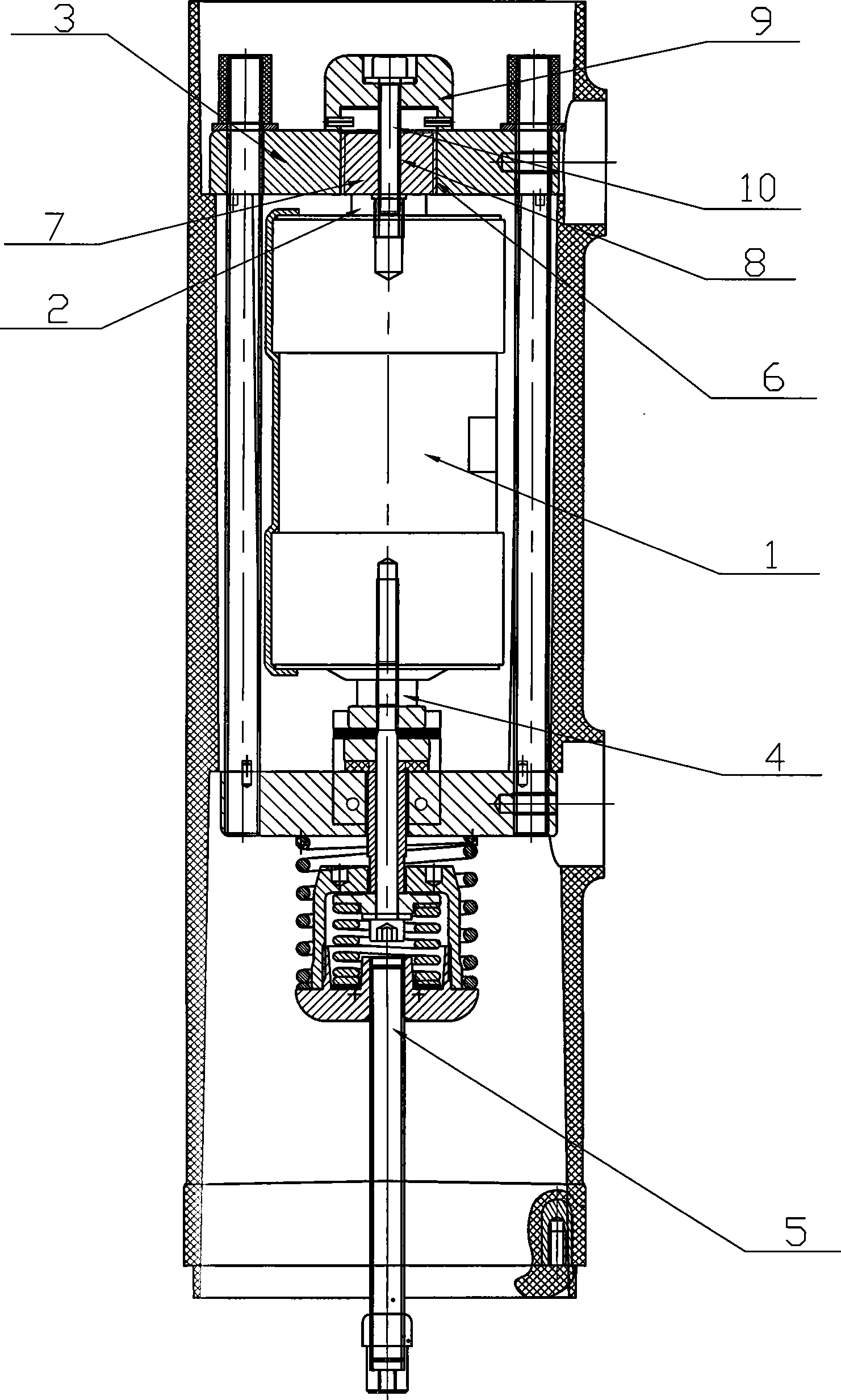
[0008] Such as figure 1 As shown, the vacuum circuit breaker of the present invention includes a vacuum interrupter 1, and the upper end of the vacuum interrupter 1 has a fixed conductive plate 3 for conductive connection with the static contact 2, and the conductive plate 3 is electrically connected to the circuit breaker. Bracket connection, the moving contact 4 at the lower end of the vacuum interrupter is connected to the transmission part through an insulating screw 5; a threaded hole 6 is opened in the center of the conductive plate 3, and the threaded hole 6 cooperates with an adjustment block 7 with external threads, and the adjustment block There is a through hole 8 in the center of 7, and there is a pad 9 above the adjustment block 7. The edge of the pad 9 is pressed on the conductive plate 3, and a threaded bolt 10 passes through the pad 9, the adjustment block 7 and the static contact 2 in turn. Mounting screw holes on the connection.

[0009] When the threading b...


PUM


Abstract

The invention belongs to a high-voltage transmission and distribution device which relates to a vacuum breaker. The vacuum breaker comprises a vacuum explosion chamber, the upper end of the vacuum explosion chamber is provided with a fixing electric conducting plate which is used for connecting a fixed contact in an electric conducting mode, the electric conducting plate is connected with an electric conducting bracket of the breaker, a moving contact which is arranged on the lower end of the vacuum explosion chamber is connected with a driving member through an insulation screw rod, the center of the electric conducting plate is provided with a threaded hole which is matched with a regulating block with external threads, and the regulating block and the upper end of the fixed contact of the vacuum explosion chamber are connected and fixed by a fastener. Because the regulating mode of the vacuum breaker is carried out on one end of the fixed contact, parts are relatively fewer in the position, and the operation space is larger, parts which need to be disassembled are fewer too, therefore, the regulating process is simple and convenient.

Description

technical field [0001] The invention belongs to high-voltage power transmission and distribution equipment, and relates to a vacuum circuit breaker. Background technique [0002] Ordinary vacuum circuit breakers generally include a vacuum interrupter installed on a conductive support. The upper end of the vacuum interrupter is the fixed end connected to the static contact, and the lower end of the vacuum interrupter is the operating end connected to the moving contact. The operating end is connected with transmission components such as insulating screws to control the opening and closing of each phase contact. In order to adjust the opening and closing synchronism, opening and closing speed, opening distance and other indicators of the contacts of each phase, the traditional method is to remove the insulating screw at the operating end from the moving contact, and adjust it by screwing in and out of the thread. Its length is to achieve the purpose of adjusting the correspon...

Claims


Application Information

Patent Timeline
IPC IPC(8): H01H33/66H01H33/664
Inventor 戴俊潘小俊林永峰
Owner 镇江大全智能电气有限公司
Why Eureka
Try Eureka