Single slit diffraction experimental instrument

An experimental instrument and single-slit diffraction technology, applied in the field of physical experiments, can solve the problems of inconvenient adjustment of slit width, narrow width of single slit, and difficult to clean dust, so as to reduce external dust and debris from contaminating the light-blocking plate, reduce the difficulty of operation, The effect of the convenient adjustment process

Active Publication Date: 2022-07-01
CHAOHU UNIV
View PDF11 Cites 0 Cited by
  • Summary
  • Abstract
  • Description
  • Claims
  • Application Information

AI Technical Summary

Problems solved by technology

[0004] There are still some deficiencies in the existing single-slit diffraction experimental equipment. The current experimental equipment is inconvenient to adjust the slit width, which makes the operation process complicated. In addition, during the long-term storage of

Method used


Image

  • Single slit diffraction experimental instrument
  • Single slit diffraction experimental instrument
  • Single slit diffraction experimental instrument

Examples


Example Embodiment

[0029] Example 1

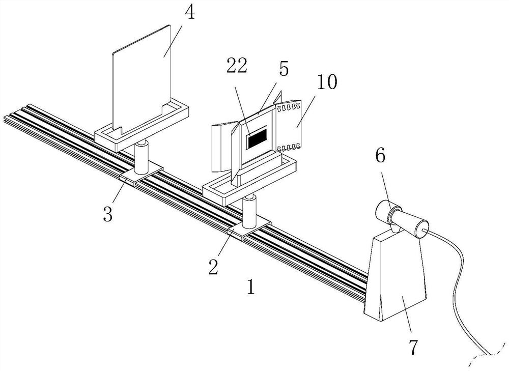
[0030] like Figure 1 to Figure 2As shown in the figure, a single-slit diffraction experimental instrument according to the embodiment of the present invention includes a slideway 1, and the top of the slideway 1 is slidably connected with a first connection seat 2 and a second connection seat 3, and the first connection The top end of the seat 2 is fixedly installed with a drive module, the transmission end of the drive module is fixedly connected with a rectangular frame 5, the drive module is used to drive the rectangular frame 5 to move horizontally, and the top of the second connection seat 3 is fixedly installed with a receiving Plate 4, one end of the slideway 1 is fixedly installed with a support base 7, and the top of the support base 7 is fixedly installed with an illumination module 6, the illumination module 6 is used for emitting test light, and the middle of the rectangular frame 5 is fixed A glass sheet is installed, a light-blocking plate 22...

Example Embodiment

[0039] Embodiment 2

[0040] like Image 6 As shown in the comparison example 1, another embodiment of the present invention is: the pressing arm 19 is arranged in a wave shape, and a magnet is fixedly installed at the end of the pressing arm 19 away from the rotating rod 18, and the pressing arm 19 is fixedly installed with a magnet. The inner side wall of the groove 16 is fixedly installed with an iron sheet. When working, it is matched with the structure of the extrusion arm 19, so that the extrusion arm 19 can fully squeeze the corresponding hose 17 during the swinging process, and at the same time, it will not affect the other hose. 17 is squeezed, and the arrangement of the magnet and the iron sheet can ensure that when the inflation bag 13 is inflated, the outgassing hose 17 is fully squeezed to ensure that the inflation bag 13 can be inflated smoothly.

[0041]When working, the light beam is emitted by the irradiation module 6, and the light beam passes through the si...


PUM


Abstract

The invention belongs to the field of physical experiments, and particularly relates to a single-slit diffraction experimental instrument which comprises a slide way, the top end of the slide way is slidably connected with a first connecting seat and a second connecting seat, a driving module is fixedly mounted at the top end of the first connecting seat, and the transmission end of the driving module is fixedly connected with a rectangular frame. The driving module is used for driving the rectangular frame to move horizontally, a receiving plate is fixedly installed at the top end of a second connecting base, a supporting base is fixedly installed at one end of a sliding way, and an irradiation module is fixedly installed at the top end of the supporting base. The driving module can be an electric telescopic rod and is matched with the single slit with the gradually-increased width formed in the light blocking plate, so that in the experiment process, the width of the single slit irradiated by light can be changed only by driving the rectangular frame to move through the driving assembly, the adjustment process is greatly facilitated, and the operation difficulty is reduced.

Description

technical field [0001] The invention belongs to the field of physical experiments, in particular to a single slit diffraction experimental instrument. Background technique [0002] Single-slit diffraction is a phenomenon in which light encounters obstacles during propagation, and light waves continue to propagate around obstacles. Diffraction is most pronounced when the wavelength is equal to or larger than the size of the slit, hole or obstacle. [0003] A Chinese patent with publication number CN108877437A discloses a single-slit diffraction experiment instrument, which includes a base plate, an LED lamp and a display board. The display board is fixed on the left end of the base plate through a first support rod. , the display panel and the slit formed by the two telescopic rods form a straight line; it is convenient for the experiment of single slit diffraction; it can consider multiple image factors of single slit diffraction, which can provide students with a good demo...

Claims


Application Information

Patent Timeline
IPC IPC(8): G09B23/22
CPCG09B23/22
Inventor 许雪艳马慧佘雪晴
Owner CHAOHU UNIV
Why Eureka
Try Eureka