Pipe end opening blockage
A technology of occluders and ports, applied in the direction of pipe components, pipes/pipe joints/fittings, mechanical equipment, etc., can solve the problems of high cost of occlusion maintenance, complicated welding process, redundant and cumbersome workload in the pressing process, etc., to achieve Improve the efficiency of plugging operation, the effect of simple and fast plugging operation
- Summary
- Abstract
- Description
- Claims
- Application Information
AI Technical Summary
Problems solved by technology
Method used
Image
Examples
Embodiment approach 1
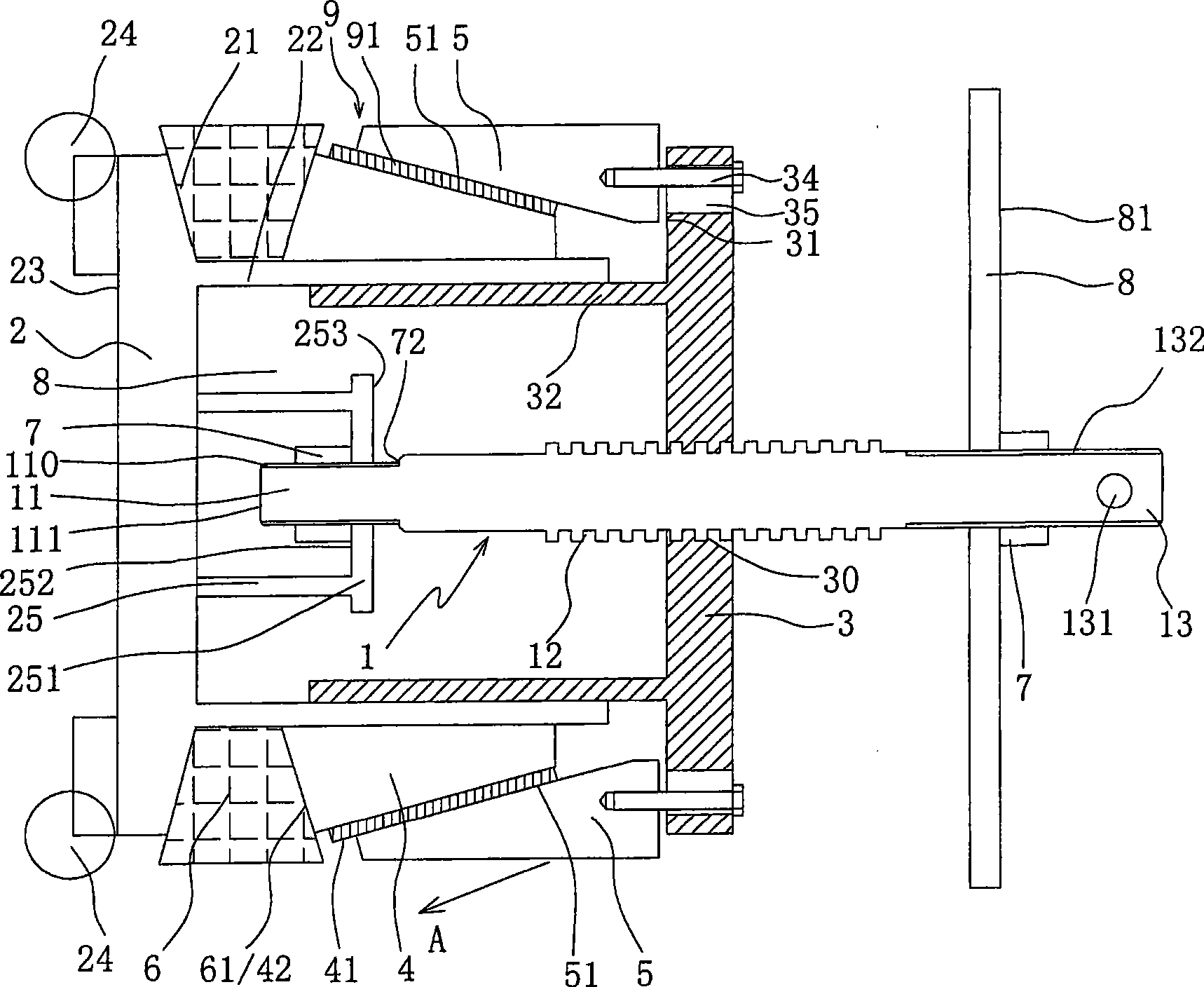
[0021] As shown in Fig. 1, a pipeline port blocker provided by the present invention includes:
[0022] A transmission screw rod 1. The transmission screw rod 1 has a pivot end 11, a threaded section 12 and an operating end 13. The operating end 13 may be provided with a perforation 131 to facilitate the insertion of the pull rod to rotate the transmission screw 1;
[0023] A pressure-bearing head 2 is pivotally connected to the pivot end 11 of the driving screw rod 1. The pressure-bearing head 2 has an inner end surface 21, an outer end surface 23 and a first cylinder portion 22 axially extending from the inner end surface 21; preferably The pivoting end 11 is restricted within the inner end surface 21 of the pressure head 2 to avoid the leakage of high-pressure medium; specifically, a support member can be fixed on the inner end surface 21 of the pressure head 2 located inside the first cylindrical portion 22 25. The supporting member 25 has a supporting end plate 251, the pivota...
Embodiment approach 2
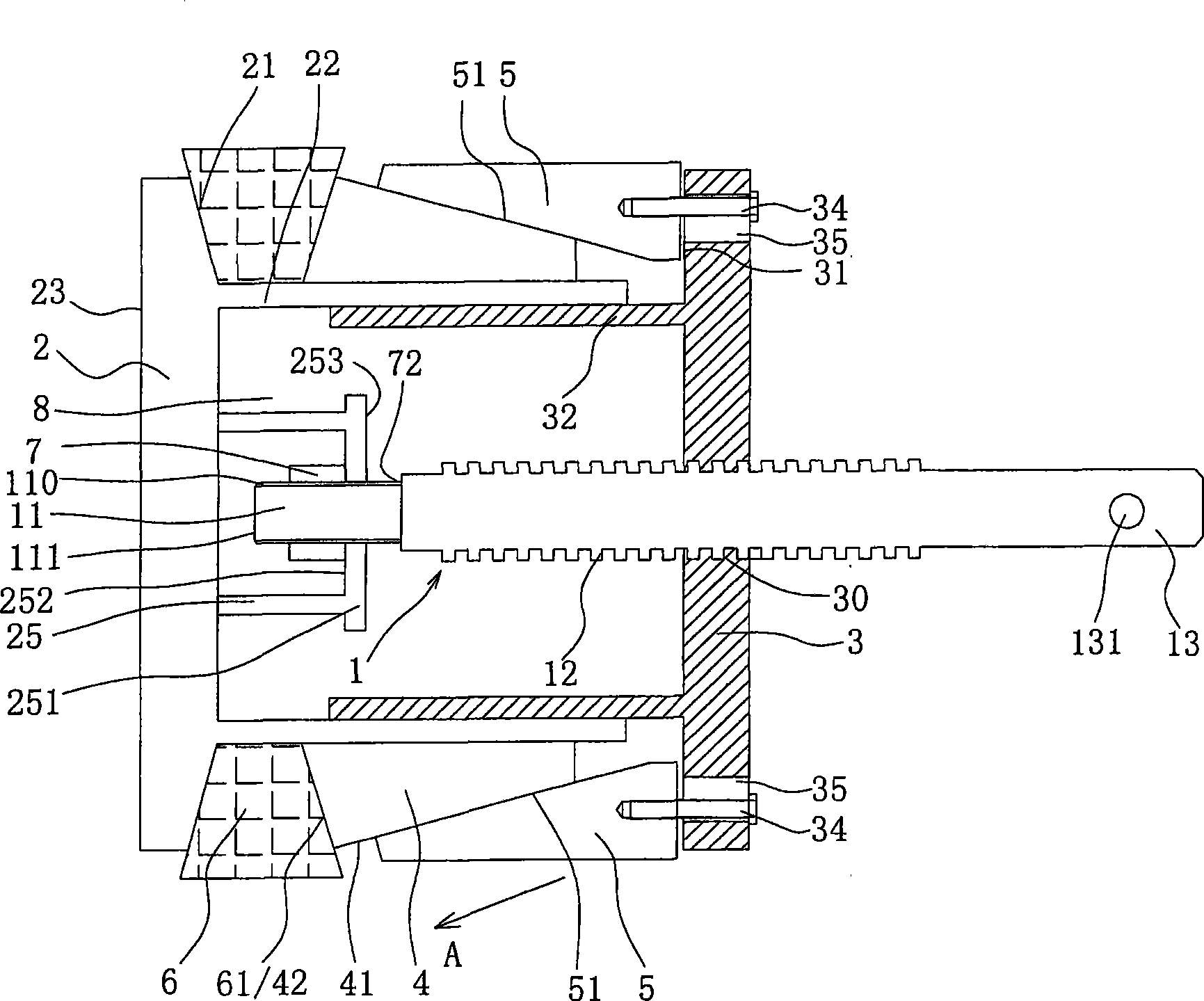
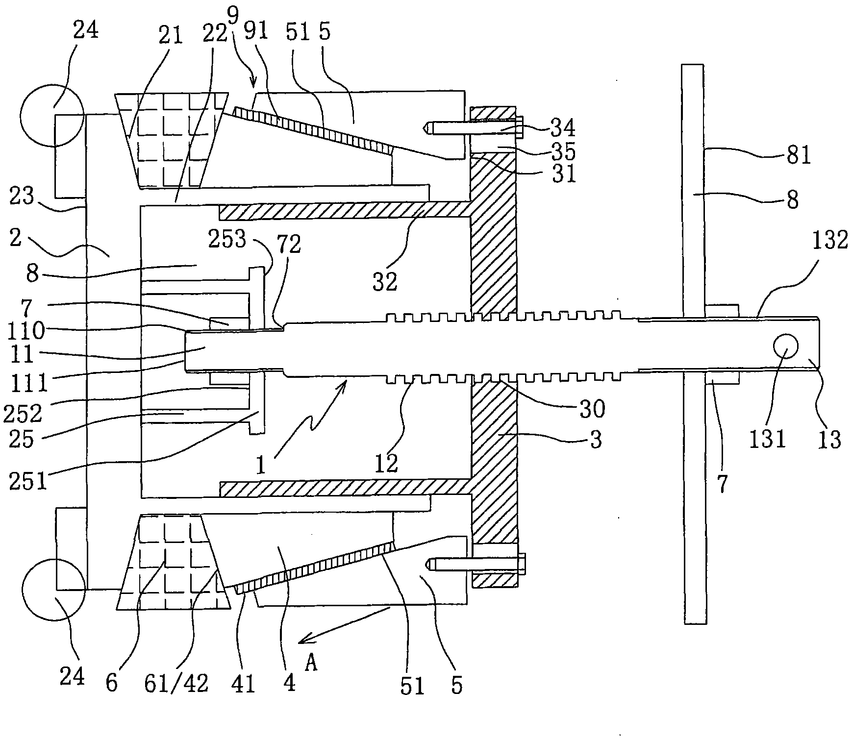
[0035] As shown in Figures 2 and 3, the structure, principle and effect of this embodiment are basically the same as those of Embodiment 1, and will not be repeated. The improvements are:
[0036] The sliding cone surface 41 of the squeeze bowl 4 and the lower surface 51 of the locking slider 5 are provided with a guide structure 9 extending in the axial direction with a concave-convex fit. The guide structure 9 includes the sliding cone surface 41 and all the locking sliders 5 The protruding strip 91 on one of the lower surface 51 and the corresponding groove 92 provided on the other, that is to say, a plurality of protruding strips or grooves need to be provided on the sliding tapered surface 41, and each locking slide Each lower surface of the block 5 is provided with a corresponding groove or protrusion. For example, a protrusion 91 may be provided on the sliding cone 41 of the squeeze bowl 4, and a recess may be provided on the lower surface 51 of each locking slider 5. The ...
Embodiment approach 3
[0040] As shown in Figure 4, this embodiment has the same structure, principle and effect as Embodiment 2, but the differences are:
[0041] The specific form of the support 25 is changed. In this embodiment, the supporting member 25 is not a cylinder, but a U-shaped frame. The U-shaped frame can also be provided with a long supporting end plate 251, and the pivoting end 11 extends through the supporting end plate 251. Into the U frame. Of course, the supporting member 25 in the present invention is not limited to the cylindrical shape in the first embodiment or the U-shaped frame in the present embodiment, any other connecting member, for example, three pillars or four pillars supporting a supporting end plate 251. Such a connecting piece is also possible without limitation, and any support frame that can provide the tensile force of the pressure-bearing head 2 relative to the actuator disk 3 can be adopted.
[0042] The convex strips 91 of the guide structure 9 are not directly...
PUM
 Abstract
Description
Claims
Application Information
 - R&D
- Intellectual Property
- Life Sciences
- Materials
- Tech Scout
- Unparalleled Data Quality
- Higher Quality Content
- 60% Fewer Hallucinations
Browse by: Latest US Patents, China's latest patents, Technical Efficacy Thesaurus, Application Domain, Technology Topic, Popular Technical Reports.
© 2025 PatSnap. All rights reserved.Legal|Privacy policy|Modern Slavery Act Transparency Statement|Sitemap|About US| Contact US: help@patsnap.com


