Improved air conditioner capillary pipe structure

A capillary and air-conditioning technology, applied in fluid circulation arrangements, refrigeration components, refrigerators, etc., can solve the problems of pipeline heat loss, affecting heat exchange efficiency, unable to ensure the uniformity of liquid separation, etc., to reduce heat loss and flow resistance. , The flow distribution is uniform, and the effect of improving the heat exchange capacity

Inactive Publication Date: 2009-03-18
SUZHOU SAMSUNG ELECTRONICS CO LTD
View PDF0 Cites 2 Cited by
  • Summary
  • Abstract
  • Description
  • Claims
  • Application Information

AI Technical Summary

Problems solved by technology

[0002] like figure 1 As shown, because the existing air conditioner has only one capillary tube, it is necessary to control two or even multiple paths in the condenser 13, and the refrigerants of the four PASS (outlet pipes) of 10, 20, 30, and 40 all pass through the capillary tube 14 after summarizing. The capillary 14 controls the flow of the four channels through the change of length, which cannot guarantee the uniformity of liquid distribution in each channel. However, for systems with small ...

Method used


Image

  • Improved air conditioner capillary pipe structure
  • Improved air conditioner capillary pipe structure

Examples


Embodiment Construction

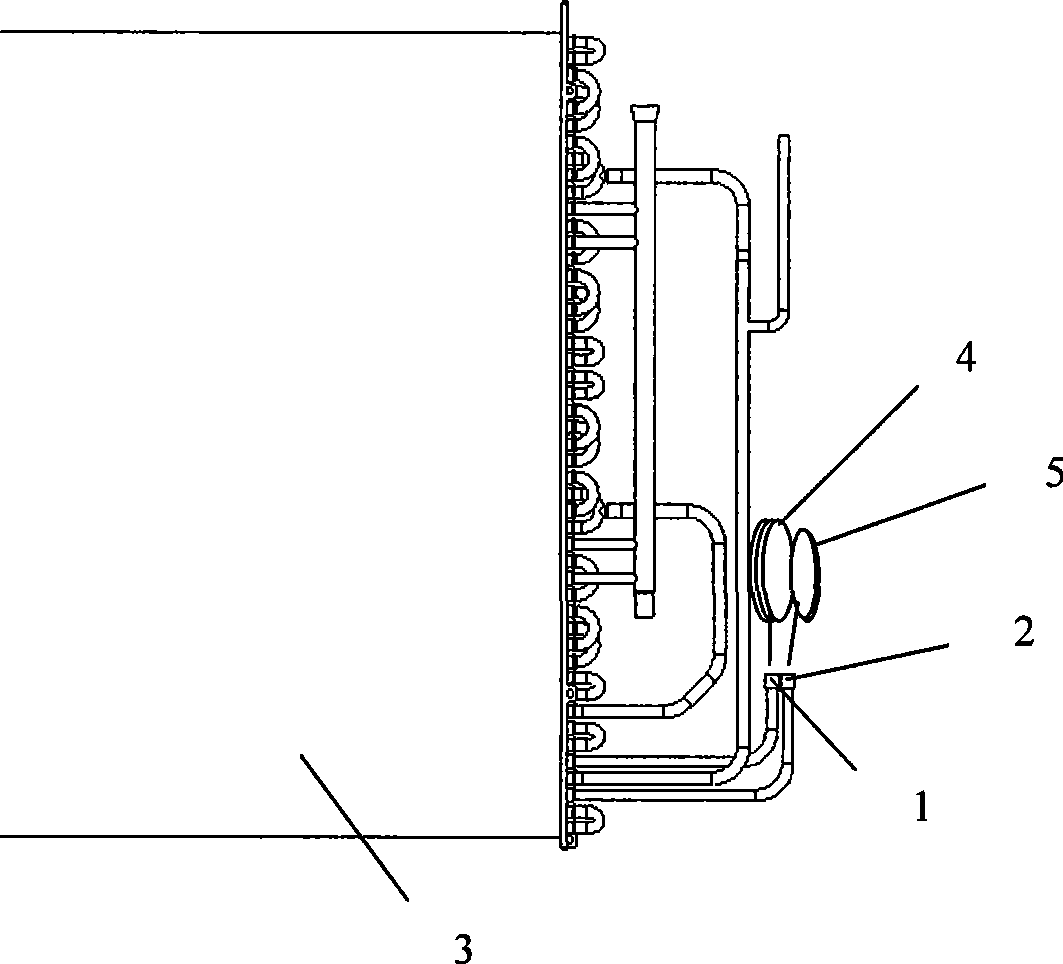
[0012] The present invention will be further described below in conjunction with the embodiments shown in the accompanying drawings.

[0013] Such as figure 2 As shown, the present invention includes a first outlet pipe 1 , a second outlet pipe 2 , a condenser 3 , a first capillary tube 4 , and a second capillary tube 5 . Wherein, the first outlet pipe 1 and the second outlet pipe 2 are close to each other, and the distance between the two depends on the space, and the assembly is enough.

[0014] The first capillary 4 connected to the first outlet pipe 1 mainly controls the flow of cold coal at the upper part of the condenser 3 and can be adjusted separately through the capillary;

[0015] The second capillary 5 connected to the second outlet pipe 2 mainly controls the cold coal flow in the lower part of the condenser 3, and can also be adjusted separately through the capillary.

[0016] The two capillary tubes directly adjust and control the flow of cold coal through thei...


PUM


Abstract

The invention provides an improved capillary pipe structure of an air-conditioner, which comprises a condenser, an outlet tube and a capillary pipe, wherein the outlet tube is connected with the condenser; the capillary pipe is connected with the outlet tube; and at least two pipelines consisting of the outlet tube and the capillary pipe are arranged. Flow paths of the pipelines are similar or approximately the same. The capillary pipe of each pipeline is a structure leading temperature of an outlet to have condensate depression close to 8 degrees; lengths or the inner diameters of the capillary pipes of the pipelines can be different to ensure that the temperature of the outlet of each pipeline has the condensate depression at about 8 degrees. The capillary pipe structure has the characteristics that branch paths of the condenser can respectively control flow, so that flow distribution can be more even; because of separated control, the length of the capillary pipe can be corresponding times longer than the prior path, thereby avoiding the problem that the capillary pipe can not be shortened any more; furthermore, because the two paths do not need to be combined into one path, heat waste and flowed friction caused by mutual heat transmission are reduced, and heat transferring capability can be greatly improved.

Description

technical field [0001] The invention belongs to the technical field of electrical appliances, and relates to an air conditioner, in particular to a capillary structure of the air conditioner. Background technique [0002] Such as figure 1 As shown, because the existing air conditioner has only one capillary tube, it is necessary to control two or even multiple paths in the condenser 13, and the refrigerants of the four PASS (outlet pipes) of 10, 20, 30, and 40 all pass through the capillary tube 14 after summarizing. The capillary 14 controls the flow of the four channels through the change of length, which cannot guarantee the uniformity of liquid distribution in each channel. However, for systems with small condensers or very uniform distribution requirements, if the distribution in the refrigeration system is uneven, it will inevitably cause tube failure. The heat loss inside the circuit will affect the heat transfer efficiency. Moreover, in order to reduce the pressure,...

Claims


Application Information

Patent Timeline
IPC IPC(8): F25B41/06
Inventor 郑寿永姚玉平黄圣祥王宏丽
Owner SUZHOU SAMSUNG ELECTRONICS CO LTD
Why Eureka
Try Eureka