Projecting zoom lens and projection display device

A technology of zoom lens and lens, which is applied in projection devices, TVs, color TVs, etc., can solve the problem of image quality degradation of reproduced images, and achieve the effect of correcting the tilt of the image plane

Inactive Publication Date: 2009-03-18
FUJI PHOTO OPTICAL CO LTD
View PDF2 Cites 10 Cited by
  • Summary
  • Abstract
  • Description
  • Claims
  • Application Information

AI Technical Summary

Problems solved by technology

[0008] However, when configured as the projection zoom lens described in Patent Documents 1 and 2 above, other aberrations, especially the tilt of the image plane, are large, so that when a high-definition image is projected, the image quality of the reproduced image deteriorates significantly.

Method used


Image

  • Projecting zoom lens and projection display device
  • Projecting zoom lens and projection display device
  • Projecting zoom lens and projection display device

Examples


Embodiment 1

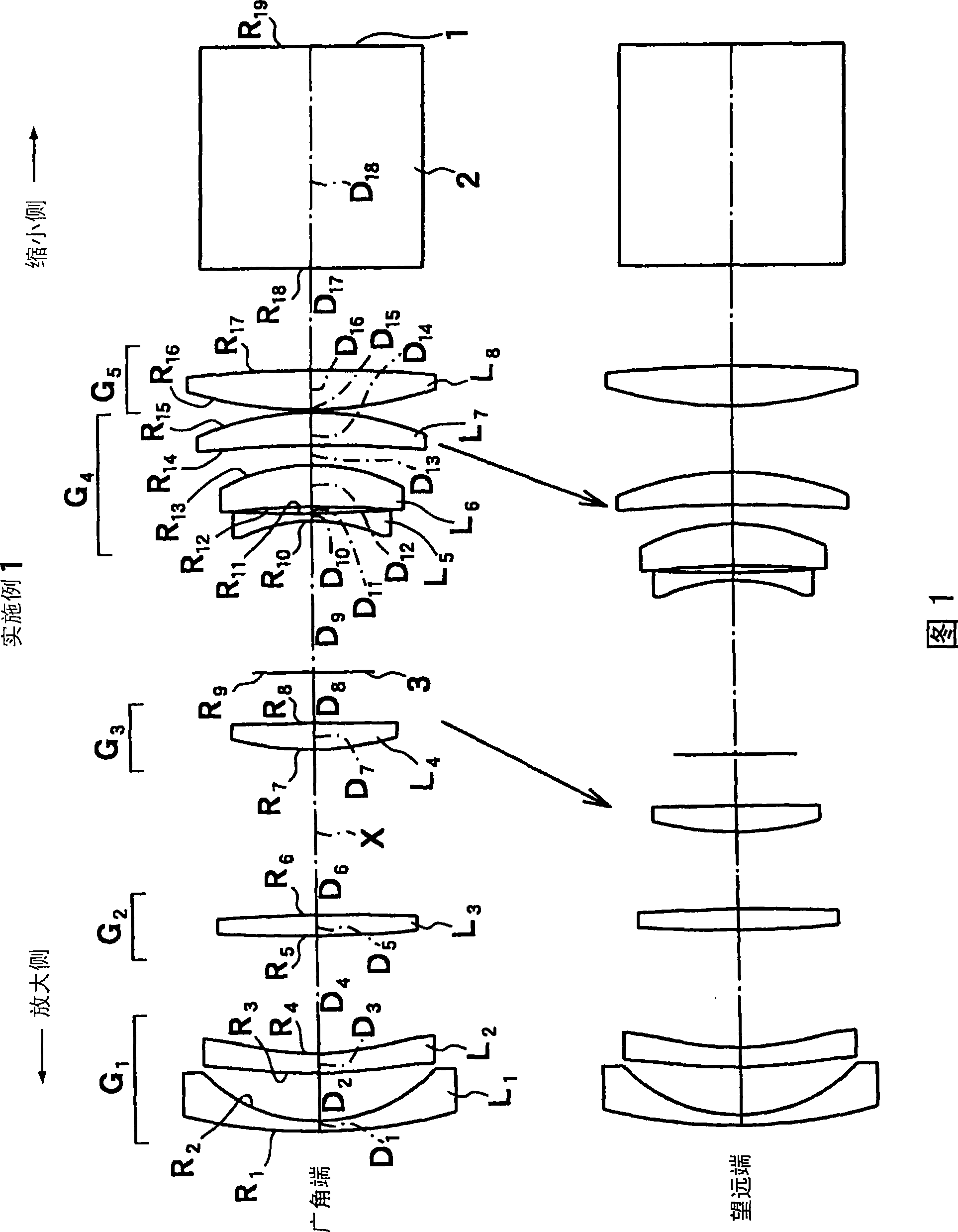
[0102] The projection zoom lens according to the first embodiment is configured as shown in FIG. 1 above. That is, this projection type zoom lens includes in order from the magnification side: the first lens group G 1 The first lens L is a negative meniscus lens whose concave surface faces the reduction side 1 And the second lens L made of aspheric lens with aspheric surface on both sides 2 constitute. Furthermore, the second lens group G 2 3rd lens L made only of biconvex lenses 3 constitute. Furthermore, the third lens group G 3 4th lens L consisting only of biconvex lenses 4 constitute. Furthermore, the fourth lens group G 4 5th lens L made of biconcave lens 5 , by following with the 5th lens L 5 The sixth lens L is a positive meniscus lens whose convex surface faces the reduction side and is arranged such that a negative air lens is formed therebetween. 6 , and the seventh lens L consisting of a positive meniscus lens whose convex surface faces the reduction sid...

Embodiment 2

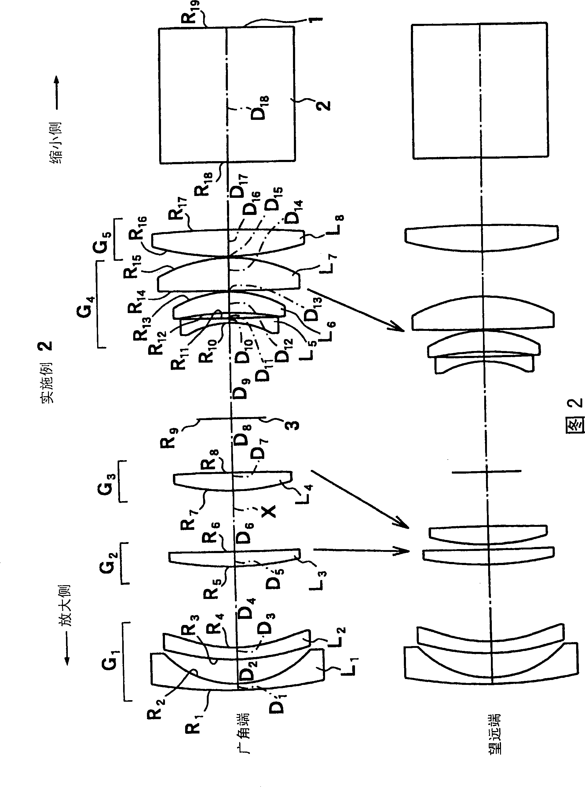
[0147] FIG. 2 shows a schematic configuration of a projection zoom lens according to the second embodiment. Although the projection type zoom lens according to the second embodiment has substantially the same structure as that of the first embodiment, the main difference is that the second lens group G is formed. 2 3rd lens L 3 Consists of a positive meniscus lens with the convex surface facing the magnification side; constitutes the 4th lens group G 4 7th lens L 7 It is made of biconvex lenses; furthermore, when zooming, the second lens group G moves from the wide-angle end to the telephoto end. 2 , the third lens group G 3 and the 4th lens group G 4 Move to the enlarged side independently of each other.

[0148] Table 2 shows the radius of curvature R of each lens surface, the center thickness of each lens, the air space D between each lens, the refractive index Nd and the Abbe number vd of each lens with respect to the d-line in Example 2.

[0149] Moreover, in the mi...

Embodiment 3

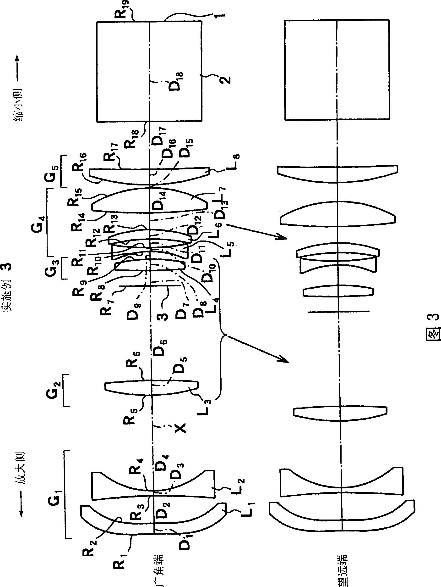
[0191] FIG. 3 shows a schematic configuration of a projection zoom lens according to the third embodiment. The projection type zoom lens according to the third embodiment has substantially the same configuration as that of the first embodiment, but the main difference is that the first lens group G 1 The first lens L made of a plastic aspheric lens with aspheric surfaces on both sides 1 With the second lens L made of biconcave lens 2 Composition; Composition of the 4th lens group G 4 7th lens L 7 Composed of biconvex lenses, constituting the 5th lens group G 5 The 8th lens L 8 Consists of a positive meniscus lens with a convex surface facing the magnification side. Further, although the aperture stop 3 is connected with the third lens group G 3 The configuration of the integral movement method is the same as that of Embodiment 1, but it is arranged in the third lens group G 3 and the second lens group G 2 are different between. Moreover, in the second lens group G 2 ...


PUM


Abstract

The invention provides a projection zoom lens and a projection display device, composed of five groups of eight lens, reaching miniaturization, lightweighting, wherein aberration particularly image surface incline can be better corrected. The device comprises a negative first lens group (G1) and respectively a positive second group (G2) to a fifth lens group (G5) from a zooming side, a reducing side is arranged to be approximately telecentric, constituted according to the way of forming a negative air lens between a fourth lens group (G4), a fifth lens group (G5) and a sixth lens group (G6). Moreover, following conditions are satisfied: 3.0 <= |fG1 / Fw| (1), -20.0 <= fn / fw <= -0.5 (2), wherein fw is an integral focus of a lens system on a wide angle end, fG1 is the focus of an aspherical lens with smallest absolute value of focal power in the first lens group (G1).

Description

technical field [0001] The present invention relates to a projection type zoom lens composed of 5 groups of 8 elements mounted on a projection display device and the projection type display device equipped with the projection type zoom lens. A projection-type zoom lens and a projection-type display device that magnify and project the beam of image information from a light valve such as a liquid crystal display device or a DMD (Digital Micromirror Device) display device onto a screen. Background technique [0002] In recent years, projection display devices using light valves such as liquid crystal display devices and DMD display devices have become widespread. In particular, three of these light valves are used, and the illumination lights of each of the three primary colors of RGB are respectively controlled. Modulation is performed, and the light modulated by each light valve is combined by a prism or the like, and an image is displayed on a screen through a projection len...

Claims


Application Information

Patent Timeline
Patent Type & Authority Applications(China)
IPC IPC(8): G02B15/177G02B15/16G02B13/18G02B9/60G02B27/00G03B21/00H04N5/74
Inventor 山本力
Owner FUJI PHOTO OPTICAL CO LTD
Why Eureka
Try Eureka