
Electric power-feeding structure

A wire and electric energy technology, applied in the field of electric power transmission structure, can solve the problem that it is difficult to further ensure the accommodating space of the container 111 and the like

Active Publication Date: 2009-03-18
YAZAKI CORP
View PDF1 Cites 2 Cited by
  • Summary
  • Abstract
  • Description
  • Claims
  • Application Information

AI Technical Summary

Problems solved by technology

In the inner space of the door 101 that accommodates the window glass 102 and its lifting mechanism, it is difficult to further ensure the accommodation space of the container 111

Method used


Image

  • Electric power-feeding structure
  • Electric power-feeding structure
  • Electric power-feeding structure

Examples


Embodiment Construction

[0018] Now, referring to the accompanying drawings, preferred embodiments of the power supply structure according to the present invention will be described.

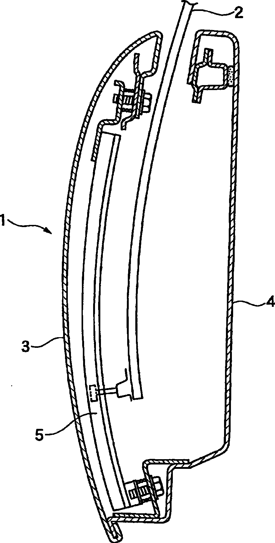
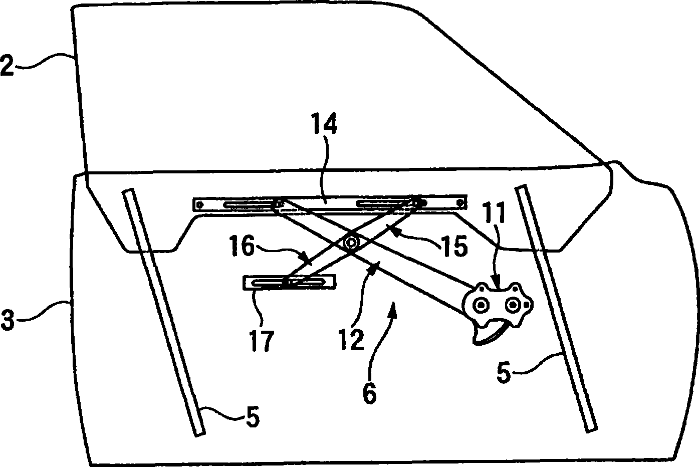
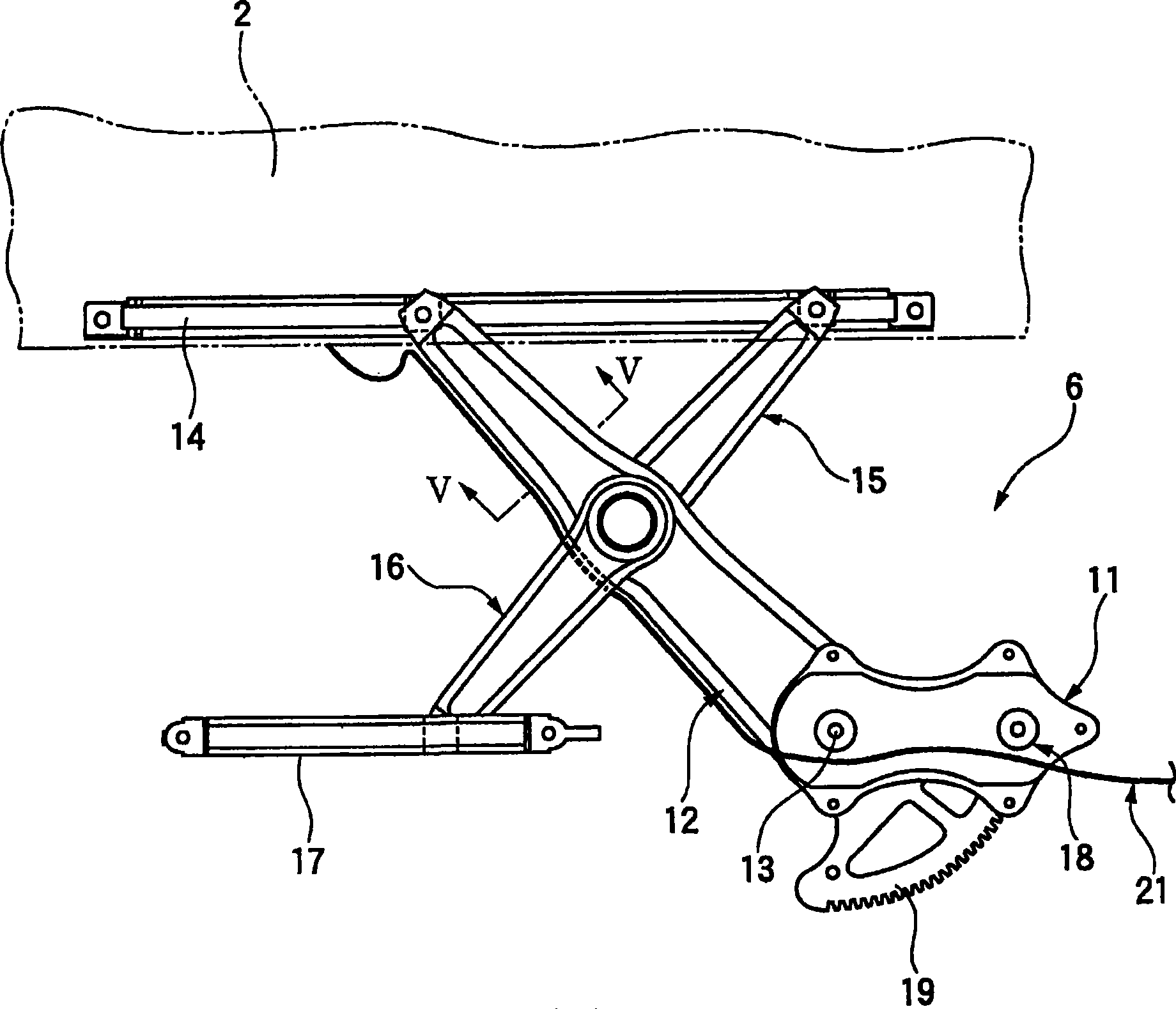
[0019] figure 1 is a sectional view of a door of an automobile to which the power transmission structure according to the present invention is applied. figure 2 is showing figure 1 Front view of the window glass raising and lowering mechanism for the door shown. image 3 yes figure 2 A detailed front view of the raising and lowering mechanism is shown, and also shows an embodiment of the power supply structure according to the invention. Figure 4 is image 3 Plan view of raising and lowering mechanism shown. 5A to 5F are image 3 Cutaway view of the arm of the raise and lower mechanism shown. 6A to 6C are diagrams showing when the window glass is raised or lowered image 3 Schematic diagram of the operation of the power supply structure shown.

[0020] Such as figure 1 with figure 2 As shown, the power ...


PUM


Abstract

An electric power-feeding structure for feeding electric power to a moving body which is driven to be raised or lowered, includes: an arm having a distal end connected to the moving body movably in a direction perpendicular to a raising or lowering direction of the moving body and a proximal end adapted to be rotatably driven so as to swing, to thereby drive the raising or lowering of the moving body. An electrical wire is routed alongside the arm, and one end of the electrical wire extending from the distal end of the arm is connected to the moving body to feed electric power to the moving body. The electrical wire is routed alongside a side surface of the arm.

Description

technical field [0001] The present invention relates to an electric power transmission structure for transmitting electric power to a moving object, which is driven to be raised or lowered, such as a window glass of a motor vehicle. Background technique [0002] In the window panes of motor vehicles, such as automobiles, power is delivered to the window panes in which heating wires are arranged, for example to prevent condensation. In the case such as a heating wire provided in a window glass that is driven to rise or fall, as a power transmission structure for transmitting power to the window glass, shown in Figure 7A with 7B The power delivery structures are generally known. [0003] exist Figure 7A with 7B In the power transmission structure shown, a movable body-side connector 105 provided on a window glass 102 and a door-side connector 106 provided in a door 101 are connected via a transmission line that transmits power to the window, which 102 is provided in the i...

Claims


Application Information

Patent Timeline
Patent Type & Authority Applications(China)
IPC IPC(8): H02G11/00
CPCH02G11/00B60R16/0215
Inventor 铃木薰山口敦吉上原建彦
Owner YAZAKI CORP
Learn More