
Method realizing asynchronous autonomous of relay and system thereof

An asynchronous autonomous, relay station technology, used in radio relay systems, transmission systems, digital transmission systems, etc., can solve the problems of secondary retransmission of error information and no feedback retransmission mechanism, so as to avoid data delay and reduce tightness. The effect of coupling

Inactive Publication Date: 2009-03-18
ZTE CORP
View PDF0 Cites 2 Cited by
  • Summary
  • Abstract
  • Description
  • Claims
  • Application Information

AI Technical Summary

Problems solved by technology

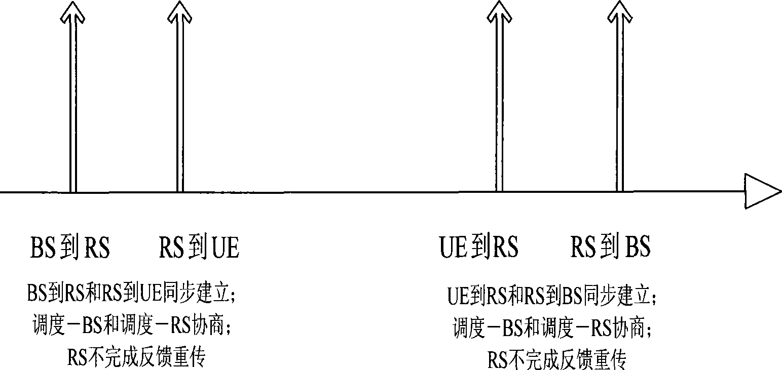
Synchronous trunk instructions such as figure 2 As shown, the so-called synchronization means that the links from BS to RS and RS to UE in the downlink direction are established at the same time, and the links from UE to RS and RS to BS in the uplink direction are established at the same time. RS may not have its own feedback retransmission mechanism, so it will lead to error messages. Second retransmission; close negotiation between the synchronous scheduling BS and the scheduling RS
Specifically, the communication link between the base station and the relay station and the relay station and the terminal needs to be established at the same time. The result is that a large amount of signaling interaction is caused by the tight coupling between the base station and the relay station scheduler; in addition, if the corresponding feedback retransmission It is only implemented in the base station, which will cause a large amount of data delay

Method used


Image

  • Method realizing asynchronous autonomous of relay and system thereof
  • Method realizing asynchronous autonomous of relay and system thereof
  • Method realizing asynchronous autonomous of relay and system thereof

Examples


Embodiment Construction

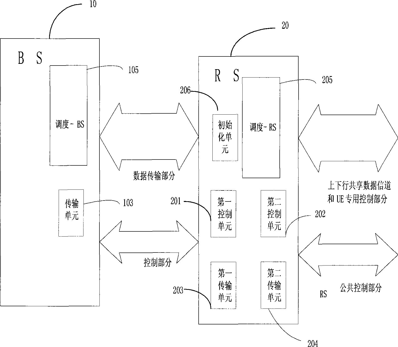
[0050] The purpose of the present invention is to provide a method and system for realizing the asynchronous autonomy of the relay station. The relay station in the present invention is configured as a non-transparent relay station with autonomous capability, and can realize two purposes of capacity allocation and coverage expansion. The method of the invention realizes the asynchrony of the link between the base station and the relay station and the link between the relay station RS and the user terminal UE.

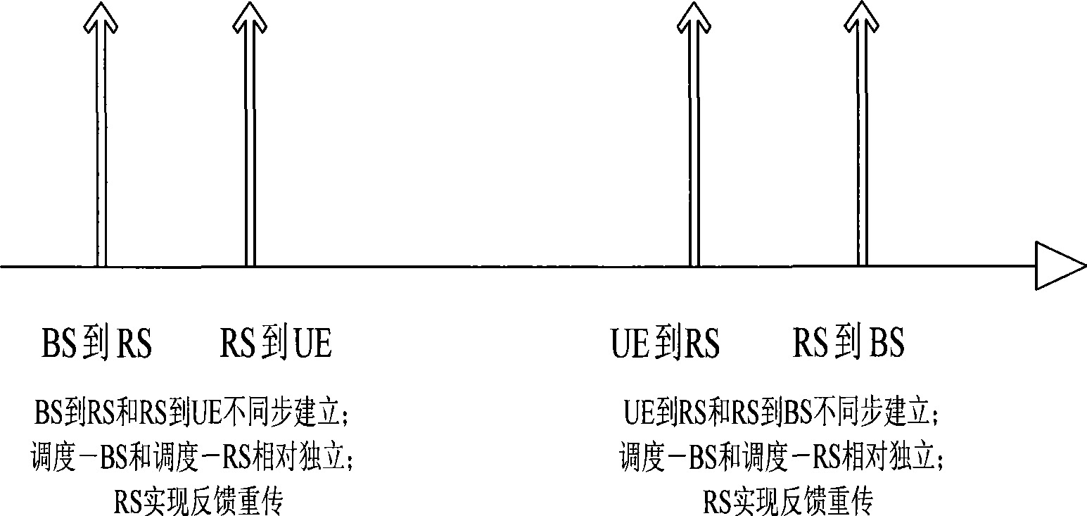
[0051] For the asynchronous autonomous relay station, the so-called autonomy means that the RS has its own scheduling and can independently transmit public control information. The so-called asynchronous, such as image 3 As shown, it means that the links from BS to RS and RS to UE in the downlink direction are not established at the same time, and the links from UE to RS and RS to BS in the uplink direction are not established at the same time. RS has its own feedback...


PUM


Abstract

The invention relates to a method for realizing the asynchronous autonomy of a relay station and a system, the method comprises the following steps: firstly, when the relay station starts to work, allocating the relay station as the asynchronous autonomy relay station, and secondly, carrying out the asynchronous relaying process between a base station and a user device by the relay station. The system comprises a first control unit for matching with the base station and finishing the singling interaction between the wireless relay station and the base station, a first data transmission unit for matching with the base station to build a bi-directional chain circuit, a second control unit for transmitting public control information to the user device, a second data transmitting unit for matching with the user device to build an up-bound and a down-bound communication channels, and a dispatching unit for maintaining the transmission between single-purpose control information and user data according to communication channel information between the wireless relay station and the user device. The method reduces the compact coupling between the base station and a dispatcher of the relay station and an amount of the signaling interaction due to the coupling.

Description

technical field [0001] The present invention relates to a method for realizing asynchronous autonomy of a relay station, in particular to a method for realizing a link between a base station (Base Station, hereinafter referred to as BS) and a relay station (hereinafter referred to as RS) and a link between a relay station RS and a user terminal UE. Asynchronous autonomous methods for roads. Background technique [0002] In the next-generation broadband wireless communication network, relay stations can be divided into the following two types according to their functions: 1. Coverage expansion form: through relay stations, uncovered areas such as blind areas or cell edges are extended through relay stations; 2. Capacity allocation form : For nomadic environments such as mobile firefighting offices or capacity allocation of different communities, the introduction of relay stations can significantly increase the coverage capacity. [0003] At present, it is generally considere...

Claims


Application Information

Patent Timeline
IPC IPC(8): H04L12/56H04L1/16H04L1/18H04B7/14
Inventor 孟彪赵建平
Owner ZTE CORP
Learn More