Multi-axial bone attachment assembly

一种组合件、多轴线的技术,应用在内部骨合成、医药科学、手术等方向,能够解决精密度不切实际等问题

Active Publication Date: 2009-03-18
WARSAW ORTHOPEDIC INC
View PDF5 Cites 6 Cited by
  • Summary
  • Abstract
  • Description
  • Claims
  • Application Information

AI Technical Summary

Problems solved by technology

While useful in some cases, the precision required to use such non-bendable devices is impractical in many therapeutic situations

Method used


Image

  • Multi-axial bone attachment assembly
  • Multi-axial bone attachment assembly
  • Multi-axial bone attachment assembly

Examples


Embodiment Construction

[0037] Reference will now be made to the embodiments illustrated in the drawings and specific language will be used to describe these embodiments. It is to be understood, however, that these embodiments do not limit the scope of the invention, and that changes or further modifications in the apparatus shown, as well as further applications of the principles of the embodiments of the invention shown herein are generally apparent to those skilled in the art to which this invention pertains. .

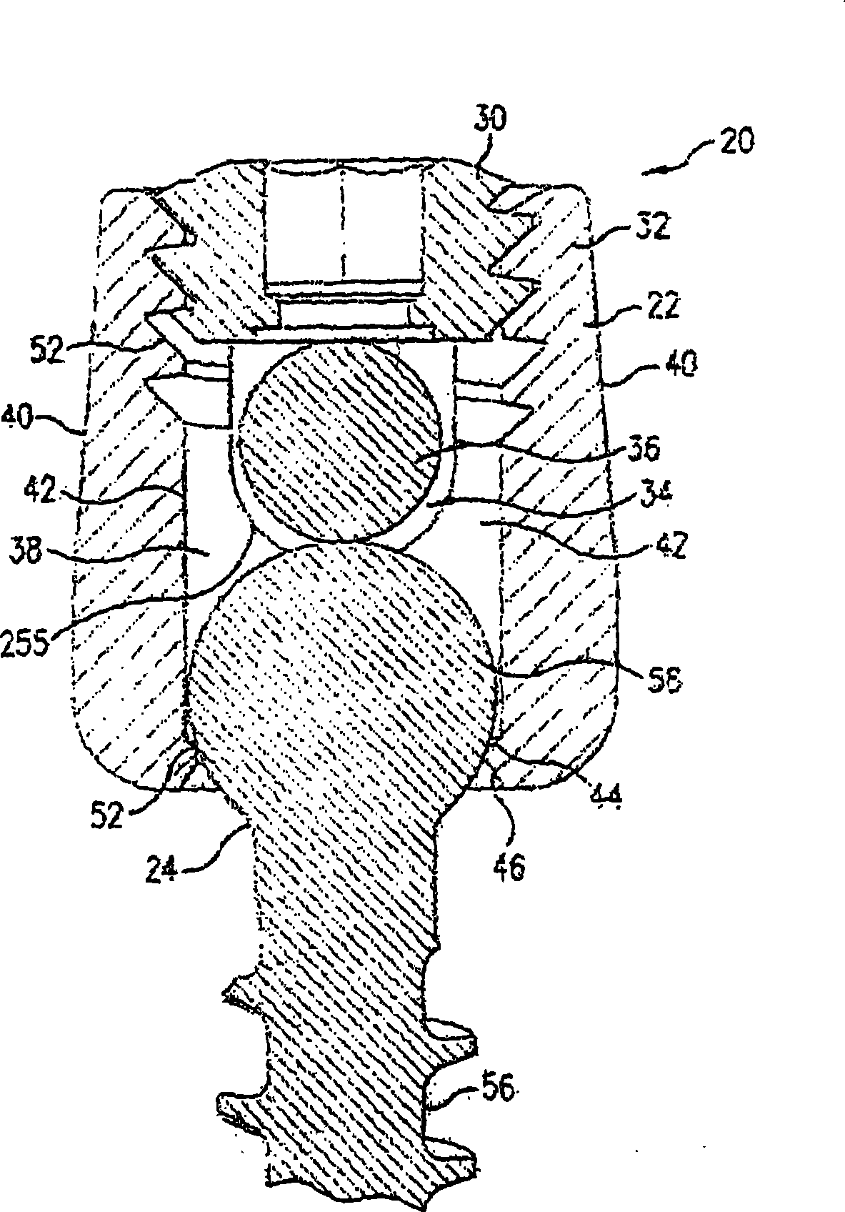
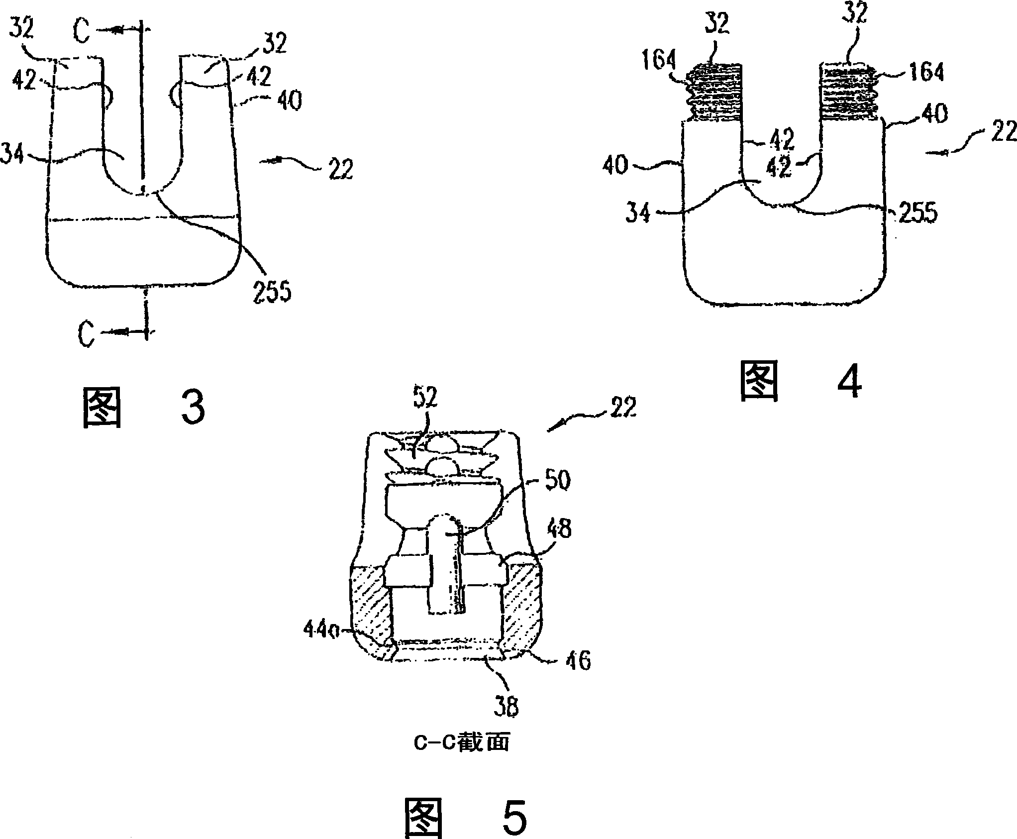
[0038] exist figure 1 One embodiment of a polyaxial bone anchor assembly 20 is shown in FIG. Bone anchor assembly 20 includes saddle element 22 , bone anchor element 24 and set screw element 30 . The saddle element 22 is generally U-shaped, its two vertical portions 32 forming a channel 34 extending through the saddle element 22 . Channel 34 is then configured to receive an elongate member 36, such as a spinal rod. To achieve posterior cervical fixation, the rod 36 can have one of a v...


PUM


Abstract

A posterior fixation system includes a saddle member and an anchoring member. The anchoring member anchors the saddle member to bone. The saddle member includes a pair of upright portions that define a channel. The saddle member further has a hole therethrough bounded by an inner wall, and the hole forms a lower opening in the saddle member. The lower opening in the saddle member may contain angular cutouts placed symmetrically about the axis of the saddle to increase the allowable angulation of the bone screw in relationship to the axis of the saddle. The channel is adapted to receive an orthopedic rod, and the hole in the saddle member is adapted to receive the anchoring member. The saddle member and the anchoring member can be coupled so as to allow multi-axial movement of the members.

Description

technical field [0001] The present invention relates generally to orthopedic implants for correcting spinal injuries or deformations, and more particularly, but not exclusively, to devices for immobilizing a portion of the spine, such as the cervical spine, thereby correcting or restoring it. Background technique [0002] In the field of spine surgery, implants are known to be placed in the vertebrae for a number of reasons, including (a) to correct abnormal curvatures of the spine, including scoliotic curvature, (b) to maintain proper spacing for fractured or damaged vertebrae and to provide bracing, and (c) other treatments on the spine. [0003] Typical implant systems utilize rods as supporting and stabilizing elements. In this implant, two or more screws are inserted into the two or more vertebrae to be implanted. Then, a rod is implanted or attached to the head of the screw, or a connecting device connecting the rod to the head of the screw is implanted, and the conn...

Claims


Application Information

Patent Timeline
Patent Type & Authority Applications(China)
IPC IPC(8): A61B17/70A61B19/00
CPCA61B17/7038A61B17/7032A61B2019/305A61B17/7037A61B2090/035A61B17/70
Inventor R·A·法利斯H·S·泰勒J·W·波伊内尔B·J·科茨
Owner WARSAW ORTHOPEDIC INC
Why Eureka
Try Eureka