Space-time coding/decoding method for pulse type multi-antenna communication system

A space-time coding, pulse signal technology, applied in radio transmission systems, transmission systems, digital transmission systems, etc., can solve the problems of complex, difficult-to-symbol pulse transmission, cannot be used for etc.

Inactive Publication Date: 2009-03-25
COMMISSARIAT A LENERGIE ATOMIQUE ET AUX ENERGIES ALTERNATIVES
View PDF0 Cites 2 Cited by
  • Summary
  • Abstract
  • Description
  • Claims
  • Application Information

AI Technical Summary

Problems solved by technology

Considering phase flipping also requires RF structures in transmit and receive, which will be more complex than using conventional pulsed systems
Finally, some UWB systems cannot be us...

Method used


Image

  • Space-time coding/decoding method for pulse type multi-antenna communication system
  • Space-time coding/decoding method for pulse type multi-antenna communication system
  • Space-time coding/decoding method for pulse type multi-antenna communication system

Examples


Embodiment Construction

[0086] The basic idea of ​​the invention is to introduce a coding diversity based on a permutation operator applied to the modulation positions of the information symbols.

[0087] In the following, we will discuss UWB transmission systems with P=2, 4, 8 transmission antennas, or more generally, with P=2, 4, 8 radiating elements. Information symbols belong to the position modulation alphabet. As mentioned above, M represents the cardinal of this alphabet.

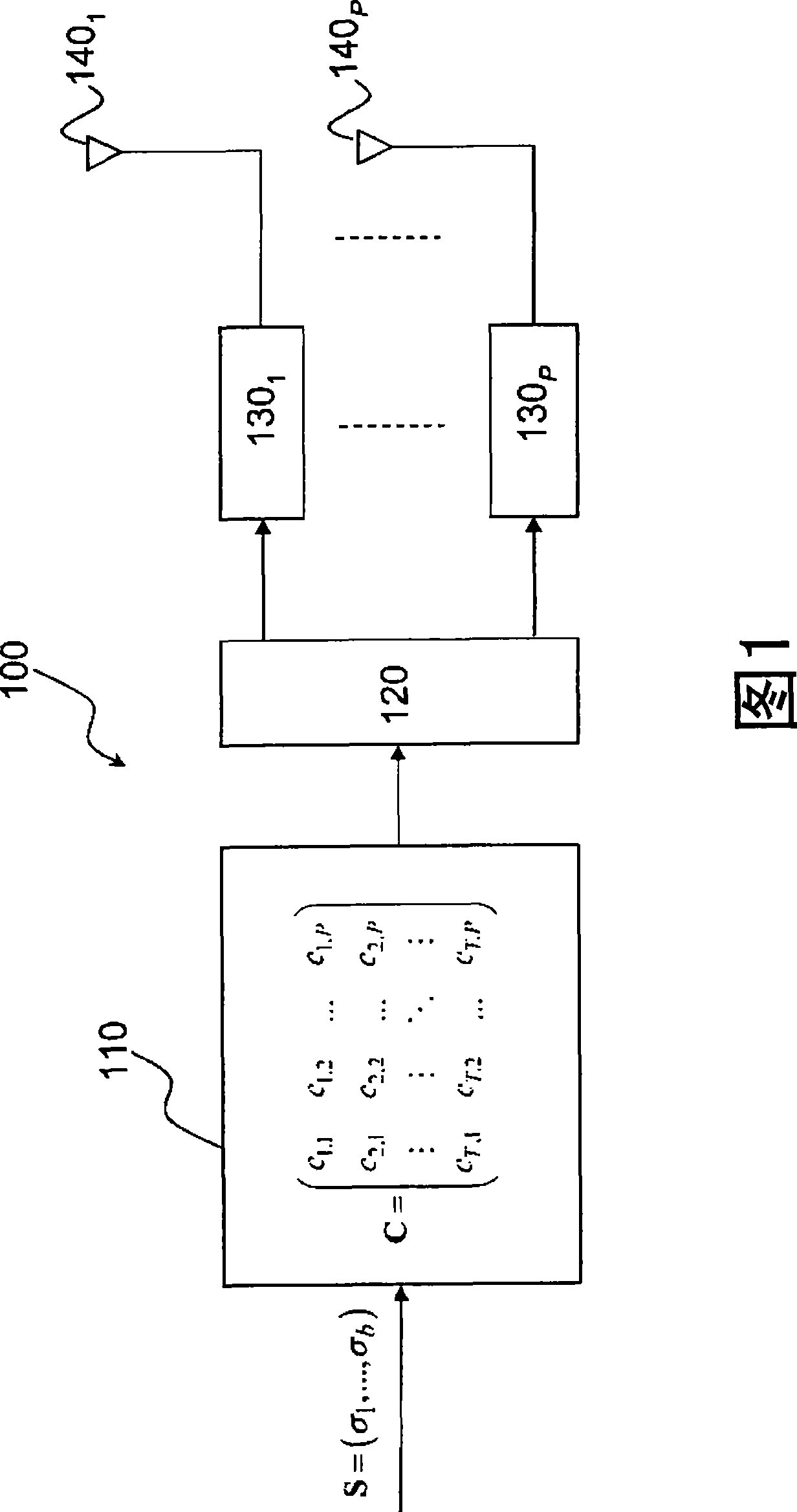
[0088] The space-time coding used by the sending device according to the invention is defined by the following matrix,

[0089] For P=2, C = σ 1 σ 2 Ω σ 2 σ ...


PUM


Abstract

The present invention relates to a space-time coding method for a UWB pulse type transmission/reception system. The space-time code, given for P=2, 4 or 8 transmission antennas, makes it possible to code 2-PPM information symbols and to modulate the position of UWB pulse signals using coded symbols, without requiring extension of the modulation alphabet. The space-time code is real with maximum diversity, and is full speed. The space-time decoding method is capable of estimating the information symbols thus transmitted.

Description

technical field [0001] The invention relates to the field of ultra-wideband UWB communication, and also relates to the field of multi-antenna space-time coding STC system. Background technique [0002] Wireless communication systems of the multi-antenna type are well known in the art. Such systems employ multiple transmitting and / or receiving antennas and are called MIMO (Multiple Input Multiple Output), MISO (Multiple Input Single Output) or SIMO (Single Input Multiple Output), depending on the type of architecture employed. In the following we use the term MIMO to cover the MIMO and MISO variants described above. The use of space diversity in transmission and / or in reception enables such systems to provide higher channel capacity than conventional single antenna systems (Single Input Single Output SISO). This space diversity is usually assisted by space-time coding and time diversity. In this encoding, the information symbols to be transmitted are encoded on several ant...

Claims


Application Information

Patent Timeline
IPC IPC(8): H04L1/06H04B1/69
CPCH04L1/0637H04L1/0625H04B7/0669H04B7/0891H04B1/7176
Inventor C·阿布耶利
Owner COMMISSARIAT A LENERGIE ATOMIQUE ET AUX ENERGIES ALTERNATIVES
Why Eureka
Try Eureka